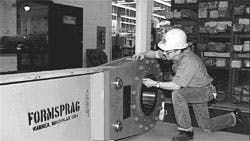
Sprag clutch shortens grinding maintenance
A 7,000-hp motor drives the stone cylinder to shred batches of a dozen or more 48-in.-long whole logs into pulp that becomes paper at the Boise Cascade plant, Ft. Frances, Ontario. Cylinder diameter is 72 in.; length, 48 in.
When the cylinder becomes sufficiently worn periodically, it must be removed and replaced. Two hub flanges, one at each end of the stone cylinder, hold the cylinder on the shaft. The flanges mount on the shaft with mating threads. As the flanges are screwed onto the shaft against the cylinder, the compressive force between them holds the stone in place. The shaft has a right-hand thread at one end; a left-hand thread at the other. With hub flanges held to prevent rotation, the shaft is turned in one direction to tighten flanges; in the opposite direction to loosen them.
The way it was
Before installation of this giant holdback sprag clutch, a large wrench was mounted on one end of the shaft when tightening or loosening hub flanges was needed. A torque arm on the wrench added leverage. Pins inserted into hub-flange outer surfaces anchored the flanges while the shaft was rotated. A bridge crane drove the torque arm to turn the shaft. Because of the long lever arm and limited practical travel with the crane, the shaft could be turned only a few degrees from starting position. The heavy wrench and torque arm then had to be removed with the crane and repositioned so the shaft could be turned a few more degrees. This process was repeated several times over a 4 to 6-hr period until the flanges were moved enough for removal or installation of a stone cylinder.
The torque needed for sufficient compressive force to hold the stone in place is 170,000 lb-ft. Torque needed to loosen the flanges is 10 to 15% more, because of interstitial bonding between flanges and cylinder, and corrosion between flanges and shaft.
No time to waste
A hydraulic cylinder now drives the torque arm to turn the shaft a few degrees from starting position with the sprag clutch engaged. Then, instead of removing the clutch, the hydraulic cylinder is reversed. The sprags disengage, and the torque arm is returned to starting position ready to turn the shaft a few more degrees. Tightening or loosening of hub flanges takes about 20 min, roughly 5 to 10% of what it took with the old system. To turn the shaft in the opposite direction, overrunning clutch position is reversed so that the shaft enters the input bore from the opposite side.
Boise Cascade engineer Dave Thompson developed a faster method of removing and installing grinding stones, using a Formsprag holdback clutch as the wrench. Once the clutch is mounted on the shaft, it need not be removed until the flanges are tightened or loosened enough.
The Formsprag holdback clutch described in this article is from Warner Electric/Dana Corp., South Beloit, Ill.
The clutch that turned into a wrench
The clutch has an inner and an outer cylindrical race with a set of sprags in the annular space between. When relative rotation between the two races is in one direction, the sprags wedge between the races, and torque transmits from one race to the other. When relative rotation is in the opposite direction, sprags tip into disengagement and the races can rotate independently with no torque transmitted.
In regular holdback applications, the inner race mounts on the headshaft or power-takeoff shaft of machinery such as a unidirectional bucket elevator drive. The outer race is held fixed. When the elevator is being driven upward, the sprags are disengaged and the headshaft rotates freely. If drive power is removed and the elevator attempts to drop due to gravity, the sprags engage instantly. That prevents reverse rotation of the headshaft and downward movement of the elevator.
The holdback clutch and torque arm on the grinder application works like a mechanic’s ratchet wrench, though on a much larger scale — It weighs 3,200 lb and has a 200,000- lb-ft torque rating! The torque arm is 14 ft long and the clutch OD and width are 30 in. and 10.6 in.
