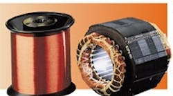
New insulation improves VFD-driven motor reliability
Increasingly, engineers are seeing premature insulation failures in the wire insulation of motors controlled by ac adjustable-speed drives that use insulated gate bipolar transistors (IGBTs). An article in our August 1995 issue, “Solutions to motor insulation failures,” p. 43, described the possible causes of premature failures and several recommended solutions. Now, there is another solution.
Chemists and engineers at Phelps Dodge Magnet Wire Co., Fort Wayne, Ind., recently announced the development of magnet wire insulation that survives longer in the electrical environments created by A-S drives than currently available wires. Called Thermaleze QS (Quantumshield), tests show that this wire resists damage from transient wave spikes, high frequencies, elevated voltage levels, and short rise-time pulses. Also, this wire is not any thicker than other magnet wires. An 18 AWG gage, for example, has an overall wire diam of 0.0432 to 0.0434 in. Insulation build is 0.0031 in. of the overall diam. Thus, it is usable in existing motor designs. The preliminary availablilty of these wires consists of round copper, heavy build, in sizes 14 to 23 AWG.
The dielectric integrity of the wire depends on its environment and mechanical forces. During an accelerated pulse test to establish relative wire life, two types of standard wire were tested along with the new wire. The test conditions were 2 kV, 20 kHz, 83 kV/msec, with a winding temperature of 90 C, at 50% duty cycle. Increased temperatures were used in these tests to obtain more timely results.
The first wire was a copper conductor, with a THEIC polyester basecoat and amideimide topcoat. It failed after 9 min of accelerated pulse testing. The second wire was the same as the first, but with triple build. It failed after 19 min of testing. The new insulation wire took over 35 hours to fail. Life for the standard wires is rated at about 25 years. See the box, (“Simulating the problem” for more information on the test.)
Some evidence confirmed
Many motor manufacturers believe that some signs of insulation failure are specific to the type of electrical stress. The tests confirmed many of these beliefs and gave evidence to support others. For example, the engineers observed two types of insulation degradation at different voltage levels:
• Localized degradation — pinhole type of fault with discolored appearance through the wire insulation surface. This type of failure tended to occur from high electric stress.
• Massive failure with carbonized degradation covering several twists. This type of failure occurred when the wire was tested at lower electric stress but high frequency.
The magnet wire insulation will be available after January 1, 1996. It can be used on non-inverter duty (general purpose) and dc motors as well.
Simulating the problem
Before creation of this magnet wire insulation, motor manufacturers needed a way to simulate the electrical stresses attributed to IGBTs, which turn voltage on and off 18,000 to 20,000 times a second.
A team of Phelps Dodge engineers and chemists, in conjunction with a major motor manufacturer, developed a test that simulates these stresses. According to Dr. Weijun Yin, the test creates reproducible and controlled pulses similar to those produced by A-S drives. The testing equipment can vary peak-topeak voltage from 1,000 to 5,000 V, frequency from 60 Hz to 20 kHz, rate of pulse rise from 10 to 83 kV/msec, and the duty cycle of the pulse from 10 to 50%.
The conventional wires used in the tests had dielectric strengths above NEMA requirements. However, the results showed that under extreme operating conditions of a motor and an A-S drive, the wires degraded rapidly under quick repetition of high frequencies, i.e. the 18 to 20 kHz. During one test that measured the effects of voltage at 2 kV, the wires lasted only 2 to 3 hours at room temperature.
Related Article
Improving Cable Reliability in Harsh Environments
Design by objective: LIFETIME & RELIABILITY
