Download this article as a PDF.
Hydraulic circuits are comprised of cylinders, valves, pumps, and are connected via hydraulic pipes and tubes. The complexity of these components are difficult to represent fully so hydraulic symbol circuits are used instead. Hydraulic symbols provide a clear representation of each hydraulic component functions. Many hydraulic symbol designs are based industry standards such as DIN24300, ISO1219-1 or -2, ANSI Y32.10 or the ISO5599. While ideally, all hydraulic circuits would use universal symbol notations, one will find differences in hydraulic circuit drawings based on the company and/or vendor. This is due to each one wanting their drawings to stand apart from other drawings found in the industry.
The symbols that represent hydraulic components typically display the following characteristics: function, actuation and return actuation methods, number of connections and switching positions, general operation principle, and simplified representation of the hydraulic flow path. Characteristics that are not included in order to simplify the circuit are the size or dimensions of the component, manufacturer of the parts, operation of the ports, physical details of the elements, and any unions or connections other than junctions. The purpose of this refresher is to help identify some of the universally accepted basic symbols that you can use to create your own drawings and read drawings from other sources.
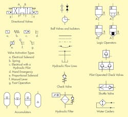
The image above highlights some of the most common symbols used for hydraulic circuits.
Hydraulic Pipes
Hydraulic flow lines are depicted as single straight lines for both pressure and return lines. Pilot flow lines are drawn as dashed or dotted lines. They only transmit pressure feed or small pilot flows. Manifold and assembly boundaries are alternating dash lines. These are used for identifying the physical limit of group valves or equipment. Hose lines are drawn as an arc with a dot at each end to indicate their connection points. A dot is also used to show where crossing lines have a physical intersecting connection with each other. If lines cross with no dot, they do not connect. Lastly, a reservoir or an open atmospheric point is shown as a cup symbol.
Ball Valves and Isolators
Double triangles are used to indicate ball valves and isolator valves. When the triangles are drawn in black the valve is normally closed and a clear triangle indicates the valve is open. The circular symbol with a two lines at a 90 degree angle is a 3-way ball valve. The symbol shows three port connections and the two lines connected are shown in the normal position. Different connection layouts can be shown in the middle of the circle to indicate layout and connection variations.
Shuttle Valve
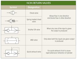
Load sensing systems commonly use shuttle valves. Their design ensures that the highest pressure is always fed to the top connection. In the symbol, there is ball valve and when it encounters two different pressures, the ball will move either way to let the maximum pressure flow towards the top connection.
Check Valves and Shut Off Valves
Check valves allow flow in only one direction. The symbol example here shows that flow goes from the top to the bottom only when the pressure is higher than the rating of the spring. A common good practice is to write the spring pressure next to the check valve.
Pilot Operated Check Valves
In the symbol example here, the dashed line is used to indicate the pilot line. The pilot line is used to open the check valve and let the flow back through the valve. The bottom symbol in the image above is a common format for a double pilot operated check sandwich plate valve. They are often used under CETOP directional valves. When pressure is applied to one side, the free flow is allowed in both directions. But when the directional valve is closed and there is no pressure applied to the valve, both check valves are closed and hold the load in place.
Directional Valves
Per ISO5599, ports on valves are marked based on a letter or number system. Here is a list of common ports and their designed markers:
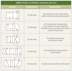
For a 4/2 way position valve, there are four pipe connections: pressure port, return port, port A and port B. The “2 position” in the 4/2 way position valve means that the valve has two switched positions meaning that it can sit in either the A or B position. For a 4/3 way position valve, there are four pipe connections but has three different possible switched positions.
Valve Activation Types
There are multiple ways to activate a hydraulic valve. The symbols above are the different ways a valve can be activated: electrical solenoid, spring, electrical with a hydraulic pilot, hand emergency, proportional solenoid, manual lever, and a foot operation.
The above image is an example of a pilot operated directional valve. This is a large high flow hydraulically operated bottom valve. It has a small electrically operated pilot valve. The solenoid valves show the hydraulic pilot, the external pilot pressure (X), and the external pilot pressure drain (Y). The symbol indicates the open center pressure (P) to return (T) spool valve.
Hydraulic Filters, Water Coolers, and Accumulators
The hydraulic filter above shows that the flow will come from the top due to the bypass check valve shown on the side. The check valve protects the circuit from over-pressurization if the filter becomes clog. The hydraulic water cooler intersects the hydraulic pipe above. The water flow paths are not depicted in the symbol but can be included.
The accumulator images in the image above indicate different stages. The first is a gas-pressurized accumulator and a diaphragm to separate the media. The second is a gas-pressurized accumulator with a bladder to separate the media. The third is a gas-pressurized accumulator with a piston. Lastly, the fourth accumulator is a backup bottle.
Logic Operators
Logic valves are available in several different options. The image above highlights four common cases. The symbols above are all of a directional control cartridge poppet valve. The top left image has a 1:1 ratio. This is indicated by the straight nature of the spool/poppet body. The top right symbol has an area ratio equal or less than 0.7. The bottom left has an area ratio of greater than 0.7. The bottom right has an area ratio equal or less than 0.7 with a damped/throttle nose.
Energy Supply, Service Units, Control Valves, and Actuators
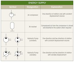
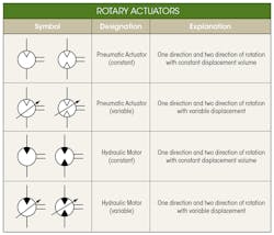
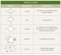
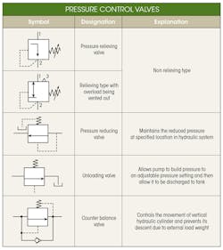
The remaining symbols below are common depictions of energy supply (i.e. pumps, compressors, and air receivers), service units (i.e. dryers, regulators, lubricators), control valves (i.e., flow and pressure), and actuators (i.e. single acting and double acting). These components are the driving force for hydraulic circuits. They regulate pressure, control flow, and also the direction of the hydraulic flow.
