Signal Conditioning and Tips for Motion Sensors
In What’s the Difference Between Vibration Sensors, we focused on the advantages and drawbacks of various types of vibration sensors on the market. In signal conditioning and tips, we address the basics of signal conditioning and tips on data acquisition system hardware selection and configuration.
Signal Conditioning
Inadequate signal conditioning can be a significant source of vibration measurement error. Signal conditioning is the manipulation of the analog signal output of a sensor to prepare it, so the data acquisition system’s digitizer can measure the signal effectively and accurately. In fact, signal conditioning is among the most important components of a data acquisition system because, unless real-world signals are optimized for the digitizer chosen, the accuracy of the measurement will be uncertain.
Signal conditioning for accelerometer-based vibration measurement can include:
Filtering: Filters reject unwanted noise within a certain frequency range. Low-pass filters are often used to block out noise in electrical measurements. Filtering can also prevent aliasing from high-frequency signals by using an anti-aliasing filter to attenuate signals above the Nyquist frequency (the minimum rate at which a signal can be sampled without introducing errors, which is twice the highest frequency present in the signal). Anti-aliasing filters are a form of low-pass filter characterized by a flat passband and fast roll-off. Because accelerometer measurements are commonly analyzed in the frequency domain, anti-aliasing filters are ideal for vibration applications.
Amplification: Amplifiers increase the signal’s voltage level to match the analog-to-digital converter (ADC) range, thereby increasing the measurement resolution and sensitivity. In addition, locating external signal conditioners closer to the signal source improves the measurement signal-to-noise ratio by magnifying the voltage level before it is affected by environmental noise.
Isolation: Electrical isolation breaks the galvanic path between the input and output signal. In this way, unwanted signals on the input line are prevented from passing through to the output. Isolation is required when a measurement must be made on a surface with a voltage potential far above the ground. Isolation is also used to prevent ground loops. Voltage signals that fall well outside the range of the digitizer can damage the measurement system and injure the operator. For that reason, isolation is usually required in conjunction with attenuation to protect the system and the user from dangerous voltages or voltage spikes.
Excitation: Many types of transducers, including accelerometers, require external voltage or current excitation. Accelerometers often have an integrated amplifier, which requires current excitation provided by the measurement device.
Linearization: Linearization involves converting a non-linear input signal to a linear output signal. It is necessary when sensors produce voltage signals that aren’t linearly related to the physical measurement.
Data Acquisition System Hardware Selection
Once the analog signal from an accelerometer (or whichever sensor type you’ve chosen) is properly conditioned, it must be converted to a digital signal and recorded. When evaluating data acquisition hardware for a specific application, consider these selection criteria:
Sensor compatibility: The sensor selection will often dictate what type of data acquisition system is appropriate based upon the sensor’s output. Does the sensor have a digital output? What is the output range? Low sensitivity sensors may require amplification of their output. A data acquisition system that can provide the excitation voltage to power the sensor can eliminate the need for external power supplies, simplifying the measurement system setup significantly.
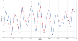
Maximum sampling rate: Best practices call for sampling the signal at a rate 10 times greater than the upper end of the frequency range of interest to capture the vibration profile accurately. For most shock and vibration measurement applications, a data acquisition system requires a sample rate of at least a few thousand hertz, but it all depends on the frequency range of interest. For example, consider the sample of vibration data recorded on a test aircraft shown in Fig. 1. The data, which was sampled at 2,500 Hz, is made up of many different frequencies, ranging from 50 to 600 Hz. However, if this same dataset were sampled only at 500 Hz (as indicated by the dashed red line), the vibration environment would appear much different and would be inaccurately represented. General guidelines on the appropriate sample rate are greater than10,000 Hz for shock testing, greater than5,000 Hz for general vibration, and ~1,000 Hz for slower vibration or movement.
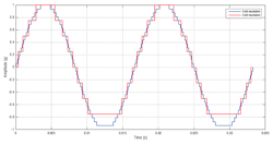
Measurement resolution: Resolution is generally specified in bits, which can then be used to calculate the resolution in acceleration units. For example, consider an accelerometer system with 16-bit resolution; in other words, it has 216 (65,536) acceleration levels or bins it can measure. Fig. 2 illustrates the importance of resolution on a simple 60 Hz sine wave with two lines of different resolutions. An instrument with 5-bit resolution provides 25 discrete acceleration levels that can be detected, while 3-bit resolution only provides 23 or 8 discrete levels. Data acquisition systems typically have resolution on the order of 16 or 24 bits. Lower quality shock and vibration data loggers, however, may only have a 12-bit resolution or less, which may not be sufficient for some applications.
Filtering capabilities: As mentioned previously, filtering removes unwanted frequency content and should be an important part of any evaluation of different data acquisition systems. High-pass filters remove lower frequency vibration and are inherent in all piezoelectric accelerometers (resistor and capacitor in series), which gives these accelerometers the AC response. Analog low-pass filters are crucial to preventing aliasing; once a signal is aliased, it can’t be filtered out digitally in software.
An ideal filter would uniformly pass all frequencies below a specified limit and eliminate all above that limit. This ideal filter would have a perfectly linear phase response to the same upper-frequency limit. But given that ideal filters don’t exist, some compromise is necessary on a filter’s amplitude and phase response.
Four main types of filters:
- A Butterworth filter is known for its maximally flat amplitude response and a reasonably linear phase response. The Butterworth filter is the most popular for vibration measurement.
- The Bessel filter has nearly perfect phase linearity, so it is best suited for transient events like shock testing. It has a fairly good amplitude response but its amplitude roll-off is slower than the Butterworth or Chebyshev filter.
- The Chebyshev filter has a faster roll-off in the amplitude response, which is achieved by introducing a ripple before the roll-off. These filters have a relatively nonlinear phase response.
- Elliptic filters have the steepest roll-off in the amplitude response, but they have a ripple in both the pass band and stop band. In addition, their phase response is highly nonlinear. This is only used for applications where phase shift or ringing are not a concern; they also have a tendency to distort complex time signals.
The best filter for a particular application will depend on the application, but in general, the Butterworth filter is best for vibration and the Bessel is best for shock testing.
Vibration Measurement System Setup
As powerful as modern data acquisition systems can be, they can be relatively expensive to purchase, can be very heavy and bulky (not very portable), require connection to an AC power supply, and an external controller to run the control and acquisition application software and to allow data storage. Many of the hardware components may not be rated for use in harsh environments where vibration measurements must be made. Finally, setting up the hardware and software required will generally require the assistance of an instrumentation expert.
Accelerometer Mounting
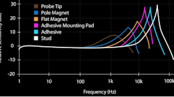
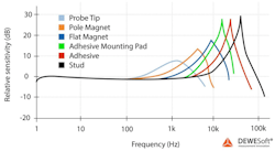
The method used to mount the accelerometer to the vibrating structure and the coupling between the sensor and the measurement point is critical to obtaining accurate results because they influence the resonant frequency of the accelerometer.
Common mounting methods
Stud mounting is the best mounting method in terms of accelerometer performance and will maximize the frequency response of the accelerometer. It’s important to torque the accelerometer down to the manufacturer’s specifications; inadequate mounting torque can reduce the frequency response. Perhaps the most important factor when stud mounting is to use a coupling fluid such as grease, oil, petroleum jelly or beeswax. Using a coupling fluid solves a lot of mounting problems, including inadequate mounting torque, surface flatness, and surface roughness.
Adhesive options vary, but the most important parameter for accelerometer performance is not the type of adhesive, but the thickness of the adhesive used.
- Loctite or a two-part epoxy offers a permanent mounting option that improves repeatability and measurement time.
- Wax or duct seal putty isn’t as effective as Loctite or epoxy but still offer surprisingly good frequency response and removal of the accelerometer is much easier.
- Double-sided tape offers the lowest frequency response of all the adhesives, but for many applications, it is still effective. The thickness of the adhesive is the most important factor.
Adhesive mounting pads offer the very high-frequency response of adhesives and stud mounting but allow swapping out accelerometers easily. For large structures, it is much easier to instrument the structure with adhesive mounting pads first, then attach the accelerometers for the test. At the end of testing, the accelerometers can easily be removed and moved to the next test project. If, after analyzing the data, the team determines more testing is needed, having the mounting pads remain on the structure ensures the tests can be repeatable. Adhesive mounting pads also prevent epoxy from damaging expensive accelerometers.
Magnetic mounting bases allow easy, mess-free accelerometer mounting on ferrous structures for short-term measurement applications. Use caution with magnetic mounting bases to avoid structural damage or personal injury.
Handheld or probe tip options are a possibility with applications that are difficult to reach for proper mounting and/or have sensitive coatings or materials that prevent using adhesives or bolting. A probe tip can be used to press the accelerometer to the structure manually; this drastically reduces the measurable frequency range to less than 100 Hz or so. They are not recommended for frequency ranges less than 10 Hz.
Wiring
Stringing the wiring needed to connect the accelerometers to the data acquisition system is both extremely time-consuming and can be difficult to accomplish in field settings. Wiring can sometimes require modifications to the test environment to accommodate the wiring from sensors to data acquisition systems to a power source. This can limit where measuring occurs and can sometimes require the use of special “test samples” designed for measurement, not field use. Test data must often be acquired on site, rather than in a lab or on a test bench.
Wiring also can introduce undesirable mechanical, electrical, and electromagnetic noise, which can compromise data quality if not taken into account. Minimizing cable lengths is generally the best way to minimize noise; a high-quality vibration data logger is also important.
Part 3 titled, “8 Environmental Factors affecting Vibration Measurement Accuracy,” of the series will address the impact of environmental factors on vibration measurement accuracy, as well as provide a short overview of vibration analysis.


