Small Parts: Design for Micro-Molding Fuels Miniature Component Applications
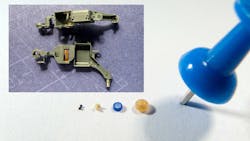
- Micro-injection molding focuses on producing small, high-precision parts and components with micron tolerances.
- Designers who are bound strictly by a set of rules will stymie their own capability and creativity.
- Understanding the material properties and the experience of matching the material with the appropriate geometry can make all the difference.
The expansion rate of miniaturized, high-precision engineering components debunks the claim that micro-molding is niche. Demand for wearable smart devices and implantable sensors enabled by small components with tight tolerances continues unabated.
Nowhere is this more evident than in the medical devices industry, where efforts to optimize form factors—smaller, faster, cheaper—are limited only by the ability to innovate. Medication delivery systems, point of care delivery systems, microfluidics and electronic components make up only a smattering of examples.
Whereas injection molding is a process for producing parts by injecting molten material into a mold, micro-injection molding focuses on producing small, high-precision parts and components with micron tolerances. In both cases, the process involves injecting molten plastic into the cavities of a steel mold. Once cooled, the parts are ejected.
Micro-injection molding also enables a high level of customization and complexity, making it suitable for specialized and miniaturized applications in the medical devices and automotive industries, where manufacturers must produce millions of parts with consistent levels of quality, precision and reliability.
Central to successful design for micro-molded components and parts is having a clear understanding of the end-user’s stated and unstated needs. That’s because producing components and devices from design parameters for small or micro parts come with a unique set of challenges and opportunities—and these are not typically associated with traditional injection molding techniques, argued Aaron Johnson, vice president of Marketing & Customer Strategy at Accumold, during a Nov. 30 Virtual Engineering Week presentation.
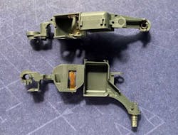
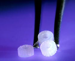
His employer, Accumold, offers tooling, molding, packaging and metrology. The company operates from a 15-acre campus near Des Moines, Iowa, where its climate-controlled facility is boasts five clean rooms. Parts and components manufactured here are commonly measured in microns; they range from micro-optic molded lens arrays and small mold pupil dilators to micro rotor pinions and micro molded gears, as well as some with micro features that may be molded in and around existing components.
As Johnson sees it, a component or manufacturing part that weighs less than a gram is considered a candidate for micro-molding and can further be defined along three criteria:
- Size: “Dealing with parts that are under a centimeter in size in many cases.”
- Micro features: “This refers to slightly larger parts with micro features. Sometimes we’ll produce a larger part that could be three or four or five centimeters big, but it has microfluidic channels in it that are 100 microns long, or deep or wide.”
- Tolerance: “That’s when positional or geometric tolerances have to be relatively perfect; we’re talking micrometers.”
Through a series of case studies, his presentation showed how knowledge of materials, processing knowledge, dimensional tolerances, thin walls, injection speed and assembly played into the design for micro-manufacturing (DfMM) process before components can be produced.
Johnson pointed out that design engineers are often able to design innovative products on screen, but that it does not necessarily translate in the molding process. “A design at the micro scale requires careful attention to what otherwise might not be a big deal for larger parts,” he said. “You can design things in CAD that you cannot mold.”
His colleagues might agree. “Some laws of physics like electrostatic induction, the triboelectric effect and Lenz Law can make a very small part not go where we need it to go, specifically, downward to the earth via gravity,” wrote his colleague Ron Baiotto in a company blog.
Throw out Traditional Rules
A common query about micro-molding is whether it has any guidelines for micro-molding. A general guideline might include the following rules:
- Thin wall sections need to be 0.004 in. (0.1 mm) or thicker and there needs to be a special focus on thick- to thin-wall transitions, as well as on wall thickness uniformity.
- Feature aspect ratios around 6:1 (although this is highly material dependent).
- Gates can be as small as 0.1 mm, and ejector pins can be a small as 0.25 mm.
- Also vital is having an understanding of how shrink rates will affect the part, and to be cognizant of parting line mismatch.
But Johnson noted that providing a set of rules can be limiting, particularly when the rules are based on principles intended for traditional injection molding. “The guidelines break down when you start to push the limits,” he said. “I asked one of our technology managers who’s been here almost 35 years: ‘What’s your guideline to give a customer on aspect ratio?’ He originally told me six to one. Then you could push him and he could say 10 to one, or eight to one—somewhere in that realm.”
The upshot, according to Johnson, is that designing micro-molded components is situational and designers who are bound strictly by a set of rules will stymie their own capability and creativity, which will restrict the outcomes. The one micro-molding design rule worth noting, he said, is to “start with your ideal…it really comes down to what you are ultimately trying to accomplish.”
Variables and Trade-offs
According to Johnson, OEMS interested in procuring micro-molded components tend to have pain points that revolve around two aspects: geometry and scale.
In terms of geometry, there are basic questions about the mechanical needs that designers should ask: Is the design a moldable shape? Can the design hit the tolerances? Is there a way to open and close or eject the component from the mold? “Sometimes there’s the notion that because it’s small, it doesn’t need some of these [parameters], and yet, the traditional rules of injection molding still apply,” said Johnson.
Some mechanical properties are inherent in the material, which is usually a starting point for design, said Johnson. In material selection, criteria such as biocompatibility, heat deflection, wear patterns or flexibility are important considerations. Accumold works with common thermoplastic materials, including PEEK, Ultem, glass-filled Nylons, and other medical grade and attenuated materials.
When a client specifies a particular material in order to meet an environmental condition, the geometry will need to be adapted to match that choice. In some instances, the processing properties of the material can make or break a project, Johnson said.
Consider PEEK (polyetheretherketone) as an example. Commonly used in implantable devices, this material is 30% glass fiber reinforced and pelletized for injection molding. The downside to using it is that it cannot fill ultra-thin areas. The same holds true for Ultem, another durable thermoplastic used in micro-optics applications, and a go-to for aerospace and automotive manufacturing.
Producing the highest-quality part requires understanding potential flaws that could affect its application, Johnson said. These details should be a part of the design for micro molding (DfMM) process at the beginning of every project. In essence, at Accumold, the DfMM process includes connecting the client with a project engineer, mold designer and a quality engineer who walk clients through the steps of the process. A considerable amount of time is spent on the front end of projects as a way to fully understand clients’ needs and requirements, he said.
Accumold also connects clients and resin suppliers so they can explore different materials that may be suited to the requirements of a unique component. “The aim is to give clients manufacturer-ready components,” he said.
And, rather than abandoning an idea that seems too complicated, Johnson’s advice is to discuss it with an expert micro molder. Understanding the material properties and the experience of matching the material with the appropriate geometry can make all the difference, he said.
About the Author

Rehana Begg
Editor-in-Chief, Machine Design
As Machine Design’s content lead, Rehana Begg is tasked with elevating the voice of the design and multi-disciplinary engineer in the face of digital transformation and engineering innovation. Begg has more than 24 years of editorial experience and has spent the past decade in the trenches of industrial manufacturing, focusing on new technologies, manufacturing innovation and business. Her B2B career has taken her from corporate boardrooms to plant floors and underground mining stopes, covering everything from automation & IIoT, robotics, mechanical design and additive manufacturing to plant operations, maintenance, reliability and continuous improvement. Begg holds an MBA, a Master of Journalism degree, and a BA (Hons.) in Political Science. She is committed to lifelong learning and feeds her passion for innovation in publishing, transparent science and clear communication by attending relevant conferences and seminars/workshops.
Follow Rehana Begg via the following social media handles:
X: @rehanabegg
LinkedIn: @rehanabegg and @MachineDesign


