How to Make Your Robots Move
Download this article in PDF format.
As robotics use continues to expand across industries from automotive and electronics to consumer goods and plastics, system designers and integrators have more choices than ever in how to implement these robots. According to the Robotic Industries Association, a new record was set in the first quarter of 2016 with more than 7,400 robots valued at $402 million ordered by North American companies alone. With regard to applications, the largest gains occurred in spot welding, assembly, and material handling.
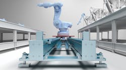
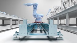
Many of these tasks are accomplished by sophisticated six-axis, articulated arm robots that can perform highly precise operations. However, the automation world sometimes requires these robots to be mobile. This is especially true in situations with production sites that have limited resources. When it comes to moving these robots into position, the most logical option is to add a seventh axis—a linear shuttle system that moves the robot to different stations to extend its operating area.
By adding a linear seventh axis, the work envelope can be expanded to the point of being able to use a smaller robot to accomplish the same work. In addition, parts can be transferred to multiple workstations at greater distances than what is possible with a static robot. In terms of efficiency, adding a seventh axis allows more machines and processes to be serviced with one robot, which has the additional benefit of reducing capital costs.
Although the idea of using a linear actuator to move a robot into position sounds simple enough, many factors go into making sure the setup is correctly sized and specified. Some of these include load capacity, speed and acceleration details, precision and accuracy, duty cycle, and lifetime requirements. Here we will explore the most important considerations.
Load Capacity
Thinking about the robot’s required load capacity is a great place to start, as these details will directly impact the loads that the actuator is required to handle as well. The robot load has two elements—dynamic and static—that must be understood before choosing the most suitable actuator.
Static loads involve those that occur when the robot is securely in place and doing its work. It is important to determine both the center of gravity and mass of the load. Will the load be picked straight up, close to the robot body, or is an extended reach required? The robot’s base must be strong enough to support the load, and sturdy and secure enough not to tip over when the robot arm reaches and moves its payload.
Load weight, deflection, and center of gravity are the most important factors to define when it comes to static loads. Future use of the robot and rail must also be considered. Think about how the robot might be used beyond the current application and plan ahead in order to accommodate higher loads. Along these lines, keep in mind that multiple robots can be mounted to the same rail as needs arise, which is another factor in determining the required load capacity.
In terms of dynamic load, which comes into play when the robot moves along its linear path, other factors must be taken into account. Some questions that you should ask yourself during design are:
• How big is the robot?
• Will a workpiece be carried along to another station?
• How fast is the robot required to move?
• How will the robot be positioned as it moves to its next work area?
A correctly sized safety margin is another critical factor that must be factored into the load calculation. In addition, hard stops must be appropriately sized so that a runaway robot would be prevented from leaving the rail if it were to run into the stop at full speed with a full load—a worst-case scenario. Once the dynamic load details are known, an actuator may be selected to meet these requirements.
For example, there are actuators that can move dynamic axial load capacities from 780 to 5,510 N and stroke lengths from 100 mm to 6 m. Traditionally, the speed of travel would be slow due to excessive weight; however, newer actuators can achieve speeds of up to 5 m/s. Furthermore, both lighter and heavier duty actuators are available to fit a wide range of robotic applications.
While making load calculations, it is also important to determine the condition of the available mounting surface. At this point, one should consider the following:
• Is the concrete thick enough to accommodate the weight and load of both the robot and rail?
• How many mounting points will be required given the available concrete?
• Is adding more concrete an option?
• Are the surfaces leveled?
• Will the target installation area allow the rail system to be leveled with the amount of adjustability provided?
If not, consider various options for leveling and enhancing the mounting surface well before installation is scheduled.
Speed and Acceleration
To match the actuator to the robot, it is vital to know the required travel speed as well as acceleration and deceleration rates. For instance:
• Will the robot be quickly moved into position to complete a pick-and place motion or assembly task and then retracted to its original position?
• Or will it move a heavy workpiece from one area to another?
It is extremely important to know these details before selecting the actuator. While some linear actuators are designed to handle heavy loads at speeds to 5 m/s, others are meant for lighter and slower operations.
Precision and Accuracy
It is very important to define the level of precision, accuracy, and repeatability required by the application. When moving a robot into position along a linear path so that it can do its job, motion must be reliable and repeatable. In fact, it is the application’s accuracy and repeatability requirements that should drive the selection of rail hardware.
Consider that additional support beams may be necessary if multiple robots will share a rail, so as to help prevent deflection during simultaneous movements. Also keep in mind that locating pins or other alignment features should be included in the rail design to give the robot a reference point for calibration. For situations that require very high levels of positioning accuracy, consider adding a linear encoder. The drive system should also be taken into account. In terms of accuracy, ball-screw-driven actuators achieve the greatest accuracy, followed by rack-and-pinion systems and then belt-driven units.
Another aspect to consider in terms of positioning accuracy is rigidity. To accomplish this, extra beams may be added along certain portions of the linear path for additional support. Think about adding beams in key areas such as pickup and drop-off points, or where the robot is required to stop and complete a vision task such as taking a picture. The idea is to carefully define what will occur along the robot’s length of travel and add rigidity as needed to improve accuracy. If these key details are not known or defined upfront, undersizing, or oversizing is likely to occur in terms of choosing the correct actuator setup for the linear seventh axis.
Duty Cycle, Lifetime, and Cable
Consider both the application’s duty cycle and cycle time as a place to start. Will the robot be used in a 24/7 operation or only a few hours each day? Also think about lifetime requirements. Does the robot need to run for two, five, or 10 years? Related to these questions are maintenance and lubrication issues for both the robot and the linear actuators it will travel along. Some actuators can go 20,000 km or more without re-lubrication whereas others need more regular attention.
Selecting the right cable is another important consideration. Most standard robot cables are not rated for repeated flexure, so keep in mind that optional cables often must be purchased. Cables should be high flex, and one must account for the bend radius and rated number of flex cycles the cable can withstand before failure. On top of that, the cable track mounting size and location must be carefully planned in advance to ensure that all necessary cabling will fit and cable track movement will not interfere with robotic movements.
Maintenance will also be impacted by the operating environment. In a dirtier setting with metal chips, sawdust, or grease, the actuator will need more protection, such as a sealed or hidden belt for felt wipers to clear debris away from the linear rails. It is important to think about paying for the amount of protection required by the application to avoid over-specifying.
Technical Help Available
In many cases, adding a linear seventh axis to an articulated arm, six-axis robot can expand the work envelope to the point of being able to use a smaller robot to accomplish the same work. Further, while specifying a shuttle system comprised of linear actuators seems simple enough, it is important to define the application in as much detail as possible. Many actuator styles and sizes are available, each with unique features suited to different applications and work environments.
Rick Wood is Managing Director at Rollon Corp., and Alex Bonaire is Product Manager at Mitsubishi Electric Automation Inc.


