This file type includes high resolution graphics and schematics when applicable.
In general, equipment designers are quite proficient at finding workarounds when a motion system is not exactly suited for an application. It’s either that, or pay a premium for a highly customized design that’s engineered to specifically address their need.
However, another way around these problems is to use the proper blend of actuator components that meet high standards for motion performance, environmental ruggedness, operational life, and cost constraints.
Environmental considerations are critically important, particularly in harsh environments. These can range from vibration and shock loading to contamination from fluids, dust, and debris. Other examples of environmental challenges include extreme temperatures, presence of a vacuum, and exposure to high humidity or corrosive atmospheres. This article reveals how some key motion components are built to withstand the abuse.
Materials
Engineers specifying a motion system should start with the right materials. Appropriate-grade stainless steel can be used for rotational bearings in wet or highly corrosive (acidic) environments. Corrosion-resistant plating, such as a hard-chrome material, also works to protect bearings and surfaces. For extremely corrosive environments, consider other bearing materials such as ceramics.
Such exotic materials, however, can prove expensive and are limited by reduced load capabilities. In some cases, engineered plastic or composite bearings can also be used if the speeds and loads permit.
Beyond material options for bearings, various methods of sealing and lubrication are needed to further protect rotational bearings. They’re discussed later in more detail.
Engineers often opt for aluminum or stainless steel as the body material for commercial motion stages used in wet environments. Various grades of stainless steel are inherently corrosion-resistant, but also relatively costly and somewhat difficult to machine.
Aluminum is a more popular material due to its low weight, ease of manufacturability (machining, extruding, and so on), and lower cost. While aluminum is generally considered to be corrosion-resistant, it will oxidize when exposed to moisture. In these instances, aluminum generates a thin oxide layer that prevents further oxidation. If scratched, the exposed aluminum will reoxidize, providing continued protection.
However, sometimes this oxidation is undesirable. In such cases, the aluminum can be anodized. Anodization provides corrosion and/or abrasion resistance, depending on the specified anodizing process. Other platings or coatings, such as nickel or epoxies, to name a few, can be used as surface treatments to prevent corrosion.
Exotic body materials, such as polymer blends or carbon-fiber pultrusions, can be employed if a lighter-weight product is desired in a corrosive environment. However, these types of materials may turn into higher-cost options.
Linear Guides
Liquids, dust, and dirt can contaminate rolling-element bearings in many linear-guidance systems, potentially reducing life and inducing premature failure of the bearing mechanisms. Particle contaminants larger than the lubricant film thickness could cause spalling or damage to the steel bearing surfaces. And lack of lubricant or exposure to moisture can permit corrosion, pitting, or etching of metal bearing components.
When considering contamination effects, engineers must be aware that several types of linear-guidance systems are available for linear stages. These options include, but are not limited to:
• Glider bearings
• Profile rail with recirculating bearings
• Round rail recirculating bearings
• Crossed roller bearings
• Guided rollers
Glider bearings consist of a bushing running on a rail. They’re often round, but can be any shape to fit a design. Profile rail with recirculating bearings are typically referred to as square-rail bearings. They include a bearing truck assembly with recirculating internal bearings. The internal bearings mate with an external guide rail to provide precision guidance. Round rail recirculating bearings, as the name indicates, run on a round rod.
These three bearing styles enable a linear bearing run on the guide rail. They are typically available with seals or wipers that hug the guide rail. These seals wipe the rail clean as the linear bearing passes over the rail, serving to both mitigate contamination onto the bearing surfaces and, in the case of rolling elements, help prevent migration of the bearing lubrication from the bearing housing.
Seals used in continuously round-rail-type bearings tend to be more effective than seals used on profile rails, due to the simplicity of the round seal shape. Profile-rail bearing seals typically consist of end seals and separate bottom seals to cover the underside of the bearings. These seals are generally more complex and, thus, more prone to contaminant entry.
Sealing options for crossed-roller bearings are limited due to the translational design of the crossed roller. Such bearings should be avoided in dirty environments.
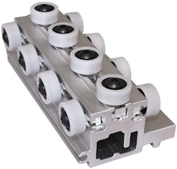
The guided-roller-style bearing arrangement has a series of wheels that run inside a track (or raceway), or series of tracks. Roller wheels typically use a rotating element bearing like a radial bearing. The bearing may have a special form on the outer diameter to mate with a rail, or a cover or wheel is added on the outside diameter of the bearing, serving as the contacting surface with a track.
Guided-roller style bearings are easy to seal, because they often implement a radial ball bearing that uses proven radial-sealing techniques. Debris tends to impact the seal tangentially, so there is low abrasion between contaminants and the seal.
In contrast, glider bearings, profile-rail bearings, and round-rail bearings push the seal against debris to remove contamination from the guide rail. This direct pushing or clearing action of the contaminants causes abrasive wear that could eventually damage the seal.
Of the five bearing methods described here, guided-roller styles are probably the best at withstanding harsh environments. Generally, the most costly aspect of this design is not the bearing itself, but, rather, the assembly labor to preload it to reduce or eliminate play and provide carriage stiffness.
Since the preloading process can be quite time-consuming, engineers need to investigate different techniques to reduce that time (i.e., costs). One cost-effective preloading approach is to allow for some level of compliant interference between rollers and track that can optimize preload and system stiffness.
Drive Trains
Common drive-train mechanisms include timing belts, ball screws, lead or acme screws, and linear motors. Others, like friction drives and rack-and-pinion drives, see less-frequent use in linear actuators.
Belt drives are quite forgiving with respect to contamination. They can operate effectively in harsh environments as long as the contaminant particles are not too large to jam the drive train, or abrasive enough to damage the belts over time.
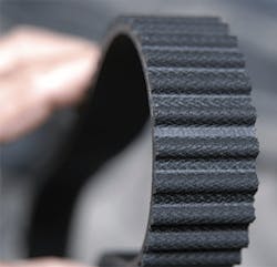
Timing belts used in linear actuators typically consist of a rubber or urethane composite that’s reinforced with braided cording running the length of the belt. Steel cords offer less stretch than Kevlar or fiberglass cords; however, avoid their use in wet environments, where cracks in the base belt material can permit water to penetrate to the cord and cause eventual corrosion and failure. Also, check the material compatibility of any fluid that will come in contact with the belt to determine if the belt material is appropriate for the fluid exposure.
Ball screws are similar to rolling-element linear bearings in that they’re also susceptible to corrosion when exposed to liquids. Exposing the system to liquids will often flush bearing lubricant from the drive train. That, in turn, exposes bearing surfaces to the liquid contaminant and leads to corrosion and premature bearing failure.
Furthermore, contamination within a ball nut can interrupt the flow of balls as they recirculate through the assembly, causing binding and/or eventual bearing failure. Seals can be added to each end of a ball-screw nut. However, the complex seal geometry required to mate to a screw thread is traditionally less than 100% effective in keeping out contamination. Thus, actuators that use ball screws need significant additional attention to minimize contamination around the ball screw.
Linear motors can work well in both wet and dirty environments, depending on the design. Contamination particle size must be managed so that debris does not cause interference at the gap between the forcer and magnet track. Generally, contamination would need to be severe to cause such interference.
An alternative configuration for harsh conditions is a linear motor with a tubular design, in which a rod extends and retracts from one or both ends of the motor body. The simplicity of the rod and body interface allows for a basic sealing device that is less prone to contamination.
Weighing Drive-System Options
Timing-belt drive systems have the advantage of low cost, long travel capability, and high speeds. When designed properly, belt-drive systems can be quite robust and provide excellent life. Generally, timing-belt drives are lower-accuracy devices when compared to screws and linear-motor systems; this is due to lower stiffness and general manufacturing limitations of belts.
Ball screws are extremely common and used in short- to medium-stroke stages. The screws can be manufactured several ways, including rolling, grinding, or whirling. Each of these processes produces screws of varying degrees of accuracy. Speed can be a limiting factor in ball screws, due to ball-recirculation dynamics as well as critical shaft-speed limitations, which are a function of screw dimensions, mass, and bearing methods used to support the screw. Ball-screw costs vary greatly, depending on precision, but generally run higher than timing-belt system costs. The key advantages of a screw versus a belt-drive design are higher precision and thrust force capacity in a smaller package.
Lead screws are produced with various thread forms and precision levels. They have critical shaft-speed limitations similar to balls screws; however, the duty cycle must be managed depending on nut and screw materials selected. It is not uncommon for a lead screw to be limited to a 25% duty cycle; all the other drive trains mentioned here can usually operate at 100% duty cycle.
In addition, lead screws require proper sizing for pressure due to thrust force and rotational speed relationships. Lead-screw manufacturers provide PV (pressure and velocity) values that engineers must adhere to when selecting the proper combinations of screw and nut sizes and materials.
Linear-motor drive trains are capable of high speeds, in addition to providing excellent accuracy and repeatability, depending on the feedback devices. Linear motors are typically used in conjunction with a linear-feedback device, whereas linear encoders are generally not required for the other drive trains mentioned. For those drive trains, motor feedback is often used to determine stage position. With the added cost of a linear encoder, linear-motor systems can be the most-expensive option of them all.
Linear-motor stages are also typically mounted so that the forcer moves along a stationary magnet track. As a result, one additional drawback to a linear-motor stage is that the forcer cables must be managed as they move. Managing the moving cables with a carrier or other device adds cost and can affect system reliability.
This file type includes high resolution graphics and schematics when applicable.
If an OEM needs a low-cost actuator, and it must function in a harsh environment, a timing-belt drive coupled with a roller-wheel guidance system can prove to be a robust combination. Assemble these components into a corrosion-resistant housing and design the body such that it limits ingress of fluids and contaminants. The result will be a motion system that provides maintenance-free operation for many years.
