This file type includes high-resolution graphics and schematics when applicable.
Rotating elements represent one of the most useful, basic, and common machinery elements. Almost every machine contains a rotating element. Among the devices we encounter every day that have rotating elements are electric motors, hard-disk drives, door hinges, and bicycles. The ubiquitous automobile is loaded with rotating elements throughout its many systems, including the often reinvented wheel.
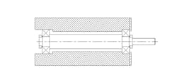
Ideally, a rotating element has just two bearings that act as point supports, as shown in Fig. 1. Recall the basic theory that pure rotation of a body occurs about an axis, which is a straight line. A straight line is defined by just two points, where in this case, those two points are defined by the centers of two bearings that support the rotating element (see “The Role of Bearings in Overconstraint” at the end of the article).
1. Two bearings aligned perfectly along a shaft are ideal. However, misalignment or the need for more than two bearings will occur in some applications.
So what is an overconstrained rotating element? Basically, it is an element that has more than two bearings supporting it. Why can this be such a bad thing? Any additional point that is not exactly on the axis as defined by the first two bearings will cause a deflection of the straight line of the axis of rotation. This bending of the shaft can trigger, among other things, fatigue failure of the shaft and unanticipated, excessive loading of the bearings.
Handling Overconstraint in Crankshafts
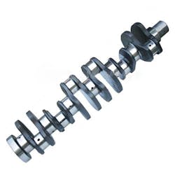
In practice, overconstrained rotating elements are very successfully used in many applications. The need for this design practice usually comes from a restriction on the diameter of the rotating element due to the application. One situation where this becomes necessary occurs in one of the most common machines in the world: the crankshaft of a multi-cylinder internal combustion engine (Fig. 2). If the crankshaft were made strong enough to handle the load from the middle pistons, it would be so large its inertia would be impractical.
So how do these powerful, high-speed machines perform so reliably with multiple bearings supporting the shaft? In this case, the answer lies in the design and very precise manufacturing techniques.
Important points from a design standpoint are that the shaft is made of a single piece of material, and the engine block that holds the bearings is also from a single piece of material. Such a design eliminates accumulation of tolerances from the assembly of multiple parts. The bores for the bearing in the engine block (housing) and bearing caps are all machined in the same setup with a process called line boring. This ensures that within very tight tolerances, the bearing bores are all on the same line, so that our theoretical straight line is very close to actually being straight.
The bearing surfaces on the crankshaft are similarly located nearly perfectly inline on a turning machine. The resulting alignment of the shaft and the bores, coupled with the slight cushioning effect of the hydrodynamic bearings, produces almost zero forces on the bearings and shaft due to misalignment. This is a fairly involved process, but when done on the production scale of common automobile engines, the cost obviously is not prohibitive.
3. A leaf hinge with its five knuckles and the body of the hinge pin are simply overconstrained journal bearings. Unlike the crankshaft, this application uses loose tolerances, low speeds, and low cycles to achieve an acceptable service life.
On the other end of the precision spectrum, we have door hinges. In this case, overconstraint is in layers. First, a hinge usually has three knuckles where the hinge pin sits, and two knuckles on the door side (Fig. 3). On top of that, most doors have three sets of hinges. Finally, the hinges are mounted by their leaves to the door on one side and the jamb on the other side, both often made of wood.
So why are door hinges obviously successful despite these seemingly large design oversights? The answer lies in the application. The speed of rotation is very slow and the life, in terms of number of cycles or revolutions, is relatively low. In addition, the clearance between the pin and the knuckle is large (compared to precision machinery), thus allowing a considerable degree of misalignment. Finally, the stiffness of the rotating member (door) is fairly low, allowing it to absorb misalignment (deform) without creating catastrophic forces on the hinges.
Feed Wheel Shaft
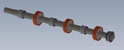
Another common rotating element—the the feed wheel shaft—comes from the world of industrial sheet-feeding machinery (Fig. 4). Due to space and inertial limitations (the shaft indexes), the shaft diameters are very small, around 1.500 inches compared to their span that often extends to 80 inches or more. The shafts can be quite straight, using commercial precision shafting.
Engine manufacturing techniques are not a good fit for manufacturing the housing, due to the long length and small bore diameter, coupled with the relatively low production volumes. One solution is to locate the middle bearings at assembly by "floating in" the bearing mounts. Oftentimes, this is done by leaving some clearance between the housing and the bearing mount and shimming it to its correct location at assembly, either with the shaft mounted on its end bearings as a guide or using optical or laser-alignment fixtures. Another common method forgoes the shimming method and instead calls for precision machining the housing and bearing holders, such that the maximum misalignment is around 0.010 in.
4. Shown is a feeding machineâs long wheel shaft that has multiple bearings along its length. This example of overconstraint is necessary due to the need to adequately support a small shaft over a considerable length. (Courtesy of SUN Automation Group)
Spring Rate and Fatigue Failure
Remember, your shaft is a spring, so typically it is an important exercise to calculate the spring rate of your shaft, perform a tolerance stack up, and determine the maximum possible misalignment. This misalignment, multiplied by the spring rate of your shaft, will give you an idea of the forces on your bearings that are in addition to your designed loads.
Always consider the direction of the misalignments and loads as well, since the two forces may be additive or potentially cancel each other to a degree. Of course, systems of multiple bearings can be statically indeterminate. However, you can still get the order of magnitude to determine if more careful examination or design changes are required.
Other consequences of high loads from overconstrained rotating elements are fatigue failure of these elements. Every revolution is a load cycle and these cycles can add up quickly in a high-speed machine.
In addition to being diligent about the bearing alignment, put into practice the use of features to minimize stress concentrations, such as radii on diameter changes on shafts instead of sharp corners. Use materials that are resistant to fatigue failure—e.g., choosing steel over aluminum—so that when you calculate the fatigue life, you have a generous factor of safety over your targeted design life. Fatigue failure is of course a large subject unto itself; excellent resources are available at ASM International.
If you must use more than two bearings, endeavor to minimize the misalignment and make sure you understand the magnitude of the forces generated by that misalignment. Then be certain your design can accommodate these additional loads without premature bearing or fatigue failure.
The Role of Bearings in Overconstraint
Several types of bearings act as point supports for rotating elements; for example, any bearing mounted in a spherical housing and some spherical roller bearings. Unfortunately, these tend to be very expensive, so they are used infrequently.
At the other end of the spectrum are very rigid bearings that by themselves define both points of an axis of rotation. This includes certain arrangements of tapered roller or angular contact ball bearings. If any other bearing is mounted on a rotating element that’s not exactly on the axis of rotation as defined by the first bearing, then it is an instance of overconstraint. Somewhere in the middle of this spectrum are the commonly used single-row ball bearings that do allow a small degree of misalignment.
Closely related to the issue of overconstraint is the angular alignment of the first bearing’s axis of rotation, with respect to the rotating element’s axis of rotation and with respect to the second bearing. This is a very important design consideration. Within each bearing’s tolerance for angular misalignment, the bearing life is determined by the external load. Going beyond the misalignment is allowable, but the amount the life can be reduced by an order of magnitude or more.


