Disaster story
Where loss of machine function may cause serious injury or even death, failure is simply not an option. Such is the case with high payload lift-and-load mechanisms for critical and hazardous materials. In one recent prototype developed in part with Thomson Industries Inc., Radford, Va., the specified linear motion component was a profile rail bearing with cylindrical roller elements, featuring a double-backed configuration with high load capacity (40,500 lbf dynamic, and 72,800 lbf static), as well as high rigidity and stiffness, anti-roll moment, and excellent precision and accuracy; carriages were made of fully hardened bearing steel, 0.75 in. thick at the thinnest region.
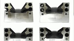
However, during initial prototype testing, the linear motion units failed spectacularly: Remnants of the fractured carriages exhibited classical characteristics of steel in shear. Failure analysis (which included a metallurgical, application, and installation review) identified an overload condition as the root cause. However, close inspection showed that the carriage material, components, quality, and overall product were all to specification. Even more troubling, the applied load was high, but within specifications (95% of the basic dynamic load rating) and while there was some lubrication starvation, this was not likely the cause of failure either. The force required to break a 6-in.-long, 0.75-in.-thick plate of through hardened bearing steel (higher than typical steel) would have to be enough to result in a stress in excess of 325,000 pounds per square inch (psi) in tension or 185,000 psi in shear; even assuming a high stress concentration factor of 4.0, an equivalent stress of 46,250 psi would still be required to shear a notched plate of through hardened bearing steel.
However, based on the application's maximum applied loads, the resultant loading at the bearings were within the bearing load capacity. Even taking into consideration a partial load bias of 66% over 33%, the maximum load one carriage received would be 38,200 lbf — less than 95% of the basic dynamic load rating or less than 52% of the static load rating, and less than 30% of a worst case shear load. The question remains: How could the bearing be overloaded to the point of shearing bearing steel?
Failure analysis
It turns out that the bearing's stiffness, pitch moment load capacity, roll moment load capacity, and high load capacity all worked to a disadvantage. The application involved a two-rail system with four carriages, meaning two carriages per rail. The rails were quite close together, as were the carriages; the carriages were within an inch end-to-end, and about two inches side-to-side. However, because the bearings were so stiff, mounting surfaces for both the rails and the carriages had to be nearly perfect — better than 0.0001-in. in flatness, straightness, and parallelism. In a perfect installation, mounting surface characteristics, rails, and carriages are straight, parallel, and have no skew or twist.
A note of caution: If the mounting surface preparation and bearing installation are not both performed properly, bearing carriages can impart various types of loads onto each other leading to what's known as an over-constrained condition.
Typically, three points define a plane, so a fourth point is redundant. Sometimes redundancy can be tolerated, but the closer carriages and rails are to one another, the more sensitive they are to mounting surface inaccuracies. Why? Because the structure has no opportunity to absorb or comply to minute differences. What would otherwise be accepted as normal loads to the carriage instead manifests itself into torque or moment loads. This is a case where flexibility and compliance beats stiff and strong.
Lesson learned: The shattered remnants of a hardened bearing steel carriage are a testament to the fact that sometimes the “oak tree” is not the best option.
Moving forward
Several linear bearing solutions and components are available today, each with features suited to different applications. For the failure scenario discussed here, two possible bearing design solutions include an S-configuration with self-aligning concavex roller bearings running on simple shafts with flats for ease of assembly and mounting, or a standard parallel de-stiffened (compliant) roller profile rail. The latter sports the “sexy” new (circa 1990s) profile rail technology, versus the former “mature” (circa 1970s) round rail technology.
A set of high load capacity, self-aligning concavex roller bearings configured to accommodate pull-off loading allows the necessary self-aligning and roll compliance to work in this application. In fact, the linear accuracy of the round rail bearing without the support rails is as accurate as a profile rail bearing. What's more, the straightness of round rail shafting in its free state is higher than profile rails, and on parity in a mounted condition, especially without a support rail.
Thanks to the compliant nature of the self-aligning round rail product, much less potential exists for an over-constrained condition, and the proximity of the bearings and rails will not result in imparting high internal pre-loads to the bearings. Therefore, the best solution for this disaster scenario is the older, more compliant round rail technology versus the newer, stiffer profile rail technology, as it is more closely matches this application's needs.
This month's failure analysis was provided by Al Ng, director of engineering for rails, guides, and components at Thomson Industries Inc. For more information, visit www.thomsonlinear.com.
