This file type includes high resolution graphics and schematics.
Piping systems are often not self-supporting because of routing, length, and weight factors. Weight loads include the weights of pipes, contents, insulation, valves, fittings, and possibly the supports. Gas, air, and steam lines that require hydraulic tests must also consider the added water weight. Restraining pipe movements from thermal expansion imposes loads on the pipe. Pressure-wave propagation from water hammer generates thrust loads on pipe sections. (See “Taming water hammer,” http://machinedesign.com/news/taming-water-hammer.) Wind can sway outdoor pipes. And earthquakes induce both vibration and differential anchor-movement loads.
Engineers need to predict and control the structural behavior of piping under various loads for a fluid system to operate reliably and safely. Time-tested industrial experience on pipe-support design can be found in Design of Piping Systems by the M. W. Kellogg Co., Houston, and ASME Codes, as listed in the accompanying references. Here are some of the fundamentals.
Pipe supports
Pipe supports in the broadest sense encompass the entire range of structural elements and mechanical devices that transmit loads from pipes to adjacent structures or the ground. They carry the weight, limit pipe movements, and manage both the stresses in the pipes and loads on equipment. A wide range of options is available to design engineers.
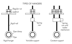
Hangers carry weight from above a pipe with the support assemblies in tension. A hanger suspends the weight of about half of the adjacent pipe spans, the riser within those spans, and the hanger assembly itself. Hangers must be adjustable while supporting the weight. Adjustment nuts and turnbuckles should have full lengths of thread engagement with locking devices. ANSI coarse threads with Class 2 allowance/tolerance are recommended. Use the root area of the external thread for stress calculations. Hangers need adequate length so that any motion does not impose large horizontal restraining forces on the pipe.
Rigid hangers (or hanger rods) are simple devices that consist of a rod, clamp, and attachment nuts. They’re suitable for pipes with limited vertical thermal movements, such as cooling water pipes.
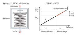
Variable supports (or variable-load spring hangers) are equipped with factory-preloaded compression coil springs. Preloaded compression springs are compact and fail-safe while tension springs are not.
Variable support is used where rigid hangers have difficulty uniformly distributing the load. Variable support gives or takes some load from its cold-set level while following thermal-induced vertical movements of the pipe. That means a portion of the load transfers to or from adjacent supports and equipment. Load variation is defined as:
Variability factor = (operating load – nonoperating load)/operating load = kΔy/Wmax.
ASME Codes recommend the variability factor to be ≤25%. Use support load and travel as the parameters for sizing a variable support. Commercially available spring hangers indicate spring compression at the approximate hot and cold positions of the piping. Springs are sized to avoid bottoming out under maximum loads. Use travel stops for hydraulic test, inspection, and maintenance of spring hangers.
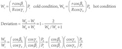
Constant supports (or constant-load spring hangers) maintain an approximately constant support force as a pipe moves vertically. Industry practice is to keep load deviation within 6% throughout the travel range. ASME defines deviation from load-test readings as:
Deviation = (maximum reading moving down – minimum reading moving up)/ (maximum reading moving down + minimum reading moving up).
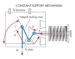
The accompanying graphic (from Design of Piping Systems by Kellogg) illustrates how a constant-support mechanism works. At a moment equilibrium of the rocker mechanism,
W(Rcosγ) = P(rcosβ).
If a pipe moves down under hot conditions, the rocker rotates counterclockwise. The shorter arm moves with a small change in moment arm, rcosβ, to increase spring load, P. The long arm moves with a large change in moment arm, Rcosγ, to afford a small change in W required to maintain equilibrium. The moment equilibriums at cold and hot conditions lead to the deviation expression:
By making the short arm nearly perpendicular to the spring rod, cosβh/cosβc ≈ 1. The sharp angle between the long arm and linkage to the pipe gives
cosγc/cosγh < 1 to partially offset
Ph/Pc>1. As a result, by appropriate choice of variables, Wh/Wc ≈1 or deviation ≈ 0 is realizable.
Constant support is most suitable for sensitive locations that require uniform supporting force, or the setup cannot tolerate transferring large portions of load to adjacent supports or equipment over the operating temperature range of pipes.
Resting supports, such as concrete saddles and welded stools, carry weight from below the pipe with the assembly mainly in compression. Supports may be fixed or slide on bases. Bolted down bases, U-bolts, or other hold-down devices provide a means for preloading. Resting a pipe directly on a support without preload could reduce service life, due to impingement or rubbing under sustained vibrations.
Restraints
Tracking dataDocumenting design calculations can be a nightmare if not done right. It is advisable to document all calculations so they’re traceable and reviewable. Traceability creates a complete “road map” of information flow, even down to narrow targets such as the paragraph of the specification, or the page, equation, or figure number of a reference. For a large drawing, write down the exact title, the drawing, revision and sheet numbers, and the coordinates for locating the object. A reviewable document requires that calculations be detailed enough for qualified people to duplicate them and understand the document without help from the originators. Computer program input lists should include all data and commands to reproduce identical outputs. Those documents are best compiled using popular software that is easy to manage. One application that fits the bill is MathCad. It improves quality and productivity by mixing text regions and calculations, enforces unit consistency to eliminate errors, and lets one set of calculations be quickly copied and modified to create another. |
Restraints resist movements to control pipe position. Pipes far from supporting structures typically use tie rods or struts. Tie rods only handle tension loads. Struts withstand tension and compression, but must not buckle.
Stops restrain translation in one or both directions along one or more axes. Guides prevent pipe rotation about one or more axes. Stops and guides are for pipes close to supporting structures. High stress in pipe due to large moments is usually accompanied by large displacements one or two sections away. Pinning down those sections using stops or guides usually reduces pipe stresses.
Anchors constrain translation and rotation of pipes in all axes. Typical anchors include equipment connections, heavy valves secured to foundations, concrete walls, and floors. Anchors can control movements of large systems or isolate influences from one zone to another.
Thermal loads
Thermal loads on anchors arise when designs restrict pipe expansion/contraction. There are three common ways to mitigate the problem:
Offsetting and loops allow room for expansion and, thus, reduce thermal load on anchors — as shown in the accompanying illustration.
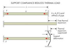
Elastic support makes an anchor slightly “flexible.” It reduces thermal load as follows:
Difficult connection-load situations are often resolved using the stiffness vector of the equipment connection in the analysis model rather than assuming it is rigid. This helps ensure a support is not overdesigned because greater rigidity increases support reactions.
This file type includes high resolution graphics and schematics.
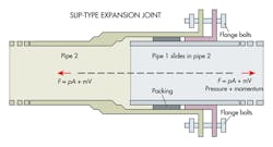
Expansion joints absorb thermal expansion or contraction to lessen loads on anchors or restraints. But restraints on both sides of an expansion joint must bear the fluid force from the pipe; and friction forces in slip type or deflection forces in corrugated expansion joints.
Resources and referencesThe piping industry has long and extensive experience in support design. In addition, a wide range of commercially available standard components let engineers choose suitable hardware for most supports. Major manufacturers of piping and support products are also good sources of technical information. And any designer of piping supports should not overlook one vital step: walk down a few piping systems to see how and why the pipes are so routed and supported. Some good references for pipe-support design include: Design of Piping Systems, The M. W. Kellogg Co., Revised Second Ed., John Wiley & Sons, Inc., 1956 Power Piping, USAS B31.1.0, USA Standard Code for Pressure Piping, The American Society of Mechanical Engineers, 1967 ASME Boiler and Pressure Vessel Code, Sec. III, Subsection NF, 1974 Ed NAVCO Piping Datalog, National Valve and Manufacturing Co., Pittsburgh PA. 1974 “Variable Spring Pipe Support Sizing,” Piping Technology & Product, Inc. Bulletin. “Expansion Joints,” U.â S. Bellows Inc. “Engineering Pipe Support, Hydraulic Snubbers,” Piping Technology & Product Inc. Bulletin, 2009. “The Mechanical Snubbers,” Piping Technology & Product, Inc. Bulletin, 2009. |
Fluid force consists of pressure and momentum components. Pressure is greatest during hydraulic testing, typically 1.3 times the design pressure. And momentum forces cannot be ignored in high-flow-velocity lines. Most support failures near expansion joints are due to neglecting the fluid force, which tends to separate an expansion joint much like a hydraulic jack.
For large pipes like a penstock, offsetting or loops are impractical. Expansion joints must be used even for environmental temperature variations and short pipes between anchors when expansion is restricted. More information on expansion joints is available from manufacturers like U.S. Bellows Inc., Houston.
Differential anchor movement arises because anchors on different foundations move at different amplitudes (and they never move in synch during earthquakes). Differential thermal movements of vessels or main pipes are similar, although they occur more slowly. Supporting pipes near connections from a vessel, or keeping the first support of a branch pipe a good distance from the run pipe, reduces loads on the connection.
Snubbers
Snubbers resist fast-acting loads much like rigid struts but allow slow thermal movement with little resistance. The devices effectively resist shock, water hammer, and earthquake loads. Snubbers are sized based on load capacity and maximum travel.
A hydraulic snubber consists of a main cylinder with a piston, and a compensation cylinder or reservoir. The main cylinder and piston rod, respectively, are connected to opposite ends of the snubber unit. A port connects valves at both ends of the cylinder. When the pipe moves slowly, the piston pushes fluid through the valves to the back side with little resistance. When the piston reaches a threshold velocity, the outlet valve closes to stop the flow and the unit behaves like a rigid strut. Reverse motion works in a similar fashion.
A mechanical snubber consists of telescoping tubes, ball nut/screws, and brake mechanisms. The tubes connected to opposite ends of the snubber support the nut and screw, respectively. The ball nut-screw pair converts linear relative acceleration between the two ends of the snubber to rotational acceleration of the screw shaft. The torque-transfer element on the shaft rotates the inertia mass through a helical torsion-spring coupling. When acceleration reaches a threshold, the inertia reaction torque tightens the spring, shrinks its diameter, and presses on a stationary mandrel to brake. The torque transfer mechanism lets the device works similarly with reverse motion. When the pipe moves slowly, the mass inertia acceleration reaction is insufficient to cause braking and both ends of the snubber can freely move in or out.
Design tips
Selecting support locations usually starts with weight balance. Designers should first position weight supports near heavy lump masses such as valves and long risers. Then space the rest of the supports outward from those locations and the anchors, always considering availability of structural members to attach supports. Estimate support spacing for weight using simple beam equations considering sag of about 0.1 in. for power piping. Or use support spacing tables in the Codes as a starting point. Then add thermal restraints to control pipe movements. And install vibration sway braces (or struts) at strategic locations — usually positions of maximum vibration displacement. Place snubbers in the longitudinal directions of long sections to bear waterhammer loads.
Structural attachments include nonintegral and integral attachments. The former include clamps, straps, U-bolts, and saddles that are bolted or otherwise connected to pipes to transmit loads. Integral attachments, such as lugs, shoes, stanchions, and trunnions are parts of supporting elements that are welded to the pipe. Welding attachments to pipes is preferred to welding them to valves, elbows, tees, or other fittings, which complicates local stresses and impairs flexibility. However, consider the compatibilities of thermal-expansion coefficients, strength, ductility, and weldability of attachments and pipe materials. A general rule is to keep the weakest link of the support assembly away from the pipe, and make supports subordinate to the pipe to protect pressure-retaining boundaries — especially when severely overloaded.
|
Nomenclature A = Flow area of pipe, in.2 |
Supplemental steel members can bridge existing supporting structures and pipe support components. These structures typically include posts, beams, and brackets built from structural steel shapes such as angles, channels, I-beams, H-beams, plates, and pipes —mainly by welding.
When designing pipe supports, use software tools and finite-element programs with caution. Calculate combined loads by adding results from concurrent load cases coordinate by coordinate. The absolute sum method is the most conservative method and justifiable if the system has both positive and negative loads. The algebraic sum method, known as the superposition principle, is applicable for static loads but leads to gross errors when combining dynamic loads because the frequencies and phase angles of dynamic responses are not tracked. As a result, the sum may be smaller than its components. The SRSS (square root of sum of squares) method is generally accepted as the most reasonable method for combining dynamic loads. Combined loads are then multiplied by safety factors to get the design loads of the supports.
A piping system is an irregular 3D structure. Determine loads on supports and stresses in pipes by considering the entire system – including masses, stiffnesses, and boundary conditions. Support design should proceed concurrently and iteratively with stress analysis of the piping system to ensure the supports are effective and model assumptions are reasonable. The final goal is to satisfy both the stress criteria of the pipe and connection load requirements of the equipment.
This file type includes high resolution graphics and schematics.
