As government regulators demand ever-lower emissions from trucks and mobile equipment, and users demand better mileage, engineers continue to explore the nuances of diesel-engine combustion. One area of intense interest involves injecting fuel into cylinders at extremely high pressure. “Higher injection pressures help with fuel-air mixing, reducing emissions and improving engine efficiency,” explains Sam Fairbanks, a technologist at Sandia National Laboratories in Livermore, Calif. “Our research partners are becoming increasingly interested in higher and higher fuel pressures.”
Researchers at the lab’s Combustion Research Facility (CRF) rely on precisely controlled hydraulics to generate the extreme pressures needed for studying fuel effects as part of a project to better understand how fuels with different chemical compositions affect diesel internal-combustion engines. “Different fuels require different injection pressures for the best performance,” says Fairbanks.
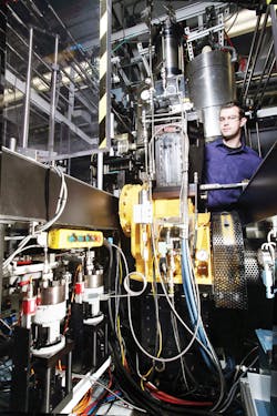
To simulate a heavy-duty diesel engine, CRF uses a diesel engine with a single, large-bore cylinder that is fed fuel from two diaphragm pumps at pressures up to 43,000 psi. Inside each pump, fuel and oil, separated by a stainless-steel diaphragm, are pressurized by a hydraulic cylinder. The cylinder compresses the oil, flexing the diaphragm and causing fuel to flow. The dual pumps cycle at 2 Hz, acting 180° out of phase to maintain a set pressure while minimizing pressure spikes. A 6-gpm pump driven by a 10-hp motor supplies the hydraulic fluid.
The Sandia team initially controlled the fuel system manually, monitoring fuel pressures with a gauge and adjusting drive pressure via a hand valve. They found that maintaining a target pressure and changing pressure setpoints proved to be extremely difficult. As an alternative, they turned to electrohydraulic motion control.
Advanced electrohydraulics
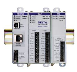
To get better precision and stability from the hydraulics, Sandia engineers opted for an RMC75 motion controller from Delta Computer Systems, Battle Ground, Wash. It uses feedback data from a pressure transducer in the fuel line to close the pressure-control loop.
The RMC also gets position feedback from linear magnetostrictive-displacement transducers (LMDTs) mounted on the hydraulic cylinders. Position inputs are needed because the hydraulic cylinders operate at varying speeds to supply the required fuel flow. Otherwise, pressure would drop a small amount as each piston reverses direction, and fuel flow would pulsate slightly.
The motion controller gets its instructions from a PC connected via an Ethernet interface. The PC runs a program Sandia engineers developed using Python, an open-source language that relies on graphic-user interfaces (GUIs) and Web and database applications to help speed programming. Sandia’s interface displays test data and lets researchers adjust engine settings, depending on the test to be run.
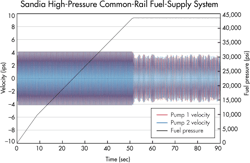
The RMC uses Delta’s RMCLink software, which integrates hydraulic motion control with Sandia’s engine-control software. “In one window we can input a target fuel pressure, and the RMC motion controller drives the pumps to maintain that pressure via closed-loop PID control,” says Fairbanks. At start-up, the PC program runs the pumps at maximum speed, relying on a PID control loop for each axis that only monitors each pump’s cylinder position, until pressure reaches the setpoint. Then the pumps slow to maintain the target pressure. The RMC75 supports two motion axes simultaneously, so a single controller can handle both diaphragm pumps.
When fuel is injected and the diesel engine starts firing, the speeds of the pumps are varied to maintain the target pressure. During this phase, the motion controller switches each axis to a mode that controls two things. First, the dynamics of cylinder motion — varying cylinder speed depending on where the piston is in its range of travel. And second, the resulting fuel pressure, which serves as an overall control for each cylinder’s motion. The motion controller must manage both parameters simultaneously, and it does this via cascaded control loops.
Cascade control
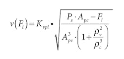
NomenclatureAPE = Cylinder size |
In the cascade control loop, an inner control loop ensures the cylinder speed is proportional to the fuel pressure. Fuel pressure, in turn, is controlled by the outer loop. In essence, the outer loop tells the inner loop how fast to index through its variable-speed ramp profile, depending on whether higher or lower fuel pressure is required to maintain pressure at the setpoint.
This inner/outer loop arrangement sounds straightforward, but a complicating factor is the compressibility of diesel fuel, which varies widely with its chemical makeup. The fuel can compress as much as 30% in volume at target pressure, while hydraulic oil compresses only about 0.5% per 1,000 psi. This factor was one reason why precise manual control of the pumps was difficult.
To deal with all the variables, Delta engineers simulated the Sandia fuel system in MathCAD. It mapped pressures into and out of the cylinders, and calculated the velocities and accelerations required for a typical test run. This helped with creating the motion-control program and tuning the gain parameters. About 20 differential equations must be solved simultaneously to simulate how the results change as a function of time, position, and other parameters.
To calculate the feed forwards (predictive terms added to the standard PID gains), Delta used the VCCM equation:
As no force is applied when retracting, the feed-forward terms used in each direction were very different. And because new control-loop gain parameters must be calculated for each pressure setting, the simulation saves a lot of tuning time, says Fairbanks.
During the tests, Fairbanks used Delta’s Plot Manager software to monitor pressure and cylinder position and ensure the system was operating properly. “The new hydraulically operated fuel system permits higher test pressures and maintains the pressure set point to within 0.5%,” says Fairbanks. “This is considerably better than the previous setup with manual controls.” Now, researchers only need to enter the pressure set point into the PC and the system will automatically establish and hold the target pressure.
Resources: Delta Computer Systems
