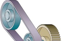
Gears and belts transmit rotary motion from one shaft to another, often changing speed and torque in the process. Gear sets are generally used where the two shafts are close together. Belts and pulleys, or sheaves, on the other hand, link shafts that are farther apart.
Gears and belts Q&A
Q. Why do some gears with enough capacity for the load develop early pitting and scuffing?
A. They may not be large enough to prevent overheating. This shortens lubricant life so it can't protect the teeth against wear. Try cooling the gearbox or using larger gears.
Q. What affect does a speed reducer have on the reflected inertia of a driven machine?
A. When a motor drives a load through a speed reducer, the inertia the motor sees is reduced by the square of the speed ratio. With a speed increaser, inertia increases, in this case, multiplied by the square of the ratio.
Q. How should you apply tension to a V-belt?
A. Apply the lowest amount of tension that prevents the belt from slipping under load. Then run the belt under full load. During the first few days of operation, retension the belt as needed to recommended values.
How they change speed
Gears: A pair of gears reduces speed in proportion to the relative number of teeth. The gear on a motor shaft is typically smaller and has fewer teeth than the one on the machine shaft. The speed ratio is R = NL/NS, where NL = number of teeth in large gear, and NS = number of teeth in small gear. If the large gear has 40 teeth and the small one 20, the speed ratio is 2:1, and the machine shaft turns once for two turns of the motor shaft. The speed is cut in half, and torque is doubled.
Belts: A belt decreases speed in proportion to the diameters of its pulleys or sheaves. The pulley on a motor shaft is typically smaller than the one on the machine shaft. The speed ratio is R = DL /DS, where DL = diameter of large pulley, and DS = diameter of small pulley.
Thus, if the diameters of the two pulleys are 40 in. and 20 in., the speed ratio is 2:1. As before, the speed is cut in half, but the torque is doubled.
