The Hidden Geometry of High-Speed Belt Drives and Linkages

The Overlooked Physics of Power Transmission
Belt drives are among the oldest and most ubiquitous mechanical power transmission elements in industrial automation. They are taught in sophomore-level machine design courses, specified from catalog pages and generally treated as solved problems. Select a profile, calculate the wrap angle, verify the service factor and move on.
This approach works at moderate speeds and loads. It fails at the velocities and precision demanded by modern fulfillment automation, semiconductor handling and high-speed packaging. At production speeds where positioning repeatability must stay within fractions of a millimeter, belt drives stop behaving like idealized rigid-body elements. They become dynamic systems with their own resonances, nonlinear compliance and geometry-dependent failure modes that conventional selection methods ignore entirely.
What makes these failure modes particularly insidious is their intermittent nature. A system that passes commissioning with perfect position accuracy may develop sporadic errors weeks later as belt temperature stabilizes, tooth surfaces wear in or production speed increases beyond the original commissioning envelope. The root causes are geometric and thermodynamic, yet engineers often chase electrical or software explanations because those are easier to instrument.
This article examines the kinematic realities that emerge when belt-and-linkage systems operate at the boundary of their performance envelope, and the geometric strategies that allow engineers to push past those boundaries without abandoning deterministic control.
Belt Geometry Under Dynamic Loading
A timing belt at low speed behaves predictably: clean tooth engagement, uniform tension distribution and a linear input-output relationship. At high speed, four phenomena emerge simultaneously, and their interaction creates the real engineering challenge.
Span resonance. Every unsupported belt span has a natural frequency determined by its tension, mass per unit length and free length. When tooth-mesh excitation frequencies approach this natural frequency, the span oscillates transversely.
The severity depends on belt material damping; polyurethane belts exhibit higher damping than neoprene, but even well-damped belts produce measurable jitter near resonance. This oscillation modulates effective span tension, which modulates tooth loading, which in turn modulates output position. The result is positional jitter that no servo tuning can eliminate because the error source is structural.
Tooth deformation and load sharing. Under dynamic loading, teeth nearest the entry point absorb disproportionate force, deforming elastically and allowing micro-slip before load transfers to adjacent teeth. The driven pulley’s angular position is not a fixed ratio of the driving pulley at the micro-positional level within a single tooth pitch. It becomes a function of load, speed, temperature and belt age.
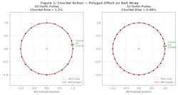
Chordal action. A timing belt wraps a pulley as a polygon, not a true circle. Each tooth engagement forms a chord and the effective contact radius oscillates with every engagement. For a pulley with N teeth, this oscillation scales with (1 – cos(π/N)), producing approximately 1.2% radial fluctuation on a 20-tooth pulley.
At high speeds, this geometric oscillation becomes a displacement excitation at tooth-mesh frequency that couples directly with span resonance, amplifying both effects where neither alone would be problematic. The countermeasure is geometric: Increasing the smallest pulley from 20 to 32 teeth reduces chordal excitation by approximately 60%.
Thermal pitch growth. Timing belts contain tension cords (steel, aramid or fiberglass) that constrain longitudinal expansion. The effective CTE of a cord-reinforced belt depends on cord material: steel-cord belts exhibit CTE on the order of 1-2 × 10⁻⁵ /°C, while aramid belts range higher at 3-5 × 10⁻⁵ /°C. A steel-cord belt operating 40°C above calibration temperature over a 500 mm span drifts approximately 0.3 mm (1.5 × 10⁻⁵ × 40 × 500).
In systems with 0.5 mm total positioning budget, thermal drift alone consumes more than half the tolerance, accumulating gradually over hours and resetting every cold start.
Why this Matters for Linked Mechanisms
In modern automation, belt drives serve as the transmission backbone coordinating motion across multiple linked axes. The architecture assumes the belt maintains a rigid kinematic connection. When that assumption breaks at high speed, positional errors amplify 2-5× at the end-effector depending on linkage geometry and instantaneous velocity ratio at the point of transfer.
The reflected inertia problem. A four-bar or slider-crank mechanism has position-dependent reflected inertia that can vary 3-10× across its stroke. The belt drive experiences cyclically varying inertial demand that shifts its dynamic response in real time. At positions where reflected inertia peaks, higher instantaneous torque increases tooth loading and shifts tension distribution, making the system’s resonant behavior position-dependent. A span safely above resonance at one linkage position may be driven closer to resonance at another.
This is a geometric problem. The linkage geometry determines how inertia maps to the input shaft. A designer who understands this mapping can configure the mechanism so peak inertial demand occurs during non-critical cycle positions, and minimum demand coincides with precision requirements.
The engineering instinct is to add closed-loop feedback. But at belt speeds of 5 m/s with 3 mm pitch (tooth mesh frequency approximately 1.7 kHz), the required correction bandwidth demands expensive hardware, consumes controller resources and creates stability risks near structural resonance. The alternative is to design the geometry so errors do not arise in the first place.
Geometric Strategies for Belt Linkage Integration
Several geometric design strategies maintain deterministic performance without brute-force feedback correction.
Span length optimization. Set span lengths so their natural frequencies fall well above or below primary excitation frequencies. Calculate tooth-mesh excitation for your operating speed range, then adjust pulley center distances or add idlers to control span length. Target a minimum separation factor of 2-3× (preferably 3× or more).
Symmetric tension distribution. In multi-span systems (H-bot, Core×Y), pulley arrangement determines tension distribution during acceleration. Asymmetric layouts create differential tensions during direction changes. Symmetric layouts eliminate this error source by geometry rather than compensation.
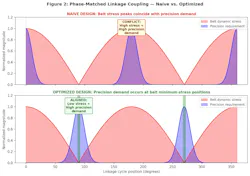
Phase-matched linkage coupling. The instantaneous velocity ratio of a linkage varies with position. A four-bar ranging from 0.8 to 1.4 in velocity ratio will amplify belt errors at its peak ratio positions. Phase the linkage so high velocity-ratio positions coincide with the belt’s lowest-error region (mid-span, constant velocity, away from entry/exit engagement). In the author’s experience, this reduces output error by 2-3× without changing components or controller tuning.
Thermal design for steady-state. Specify belt length and tension for the temperature the system reaches after 2-3 hours of operation, not ambient. The resulting drift is predictable; design the linkage so thermal offset falls within tolerance at critical transfer positions.
Case Study: High-Speed Reciprocating Systems
Consider a reciprocating mechanism driven by a timing belt where the output must achieve precise position reversal at high cycle rates. This is common in packaging, textile handling and semiconductor transfer systems.
In a naive design, the belt drives a slider connected to a reciprocating linkage. At each reversal, the belt experiences peak dynamic load: maximum deceleration, maximum tooth load and maximum span excitation. The timing of these peak loads coincides exactly with the transfer point where positional accuracy matters most. Every problematic phenomenon described above reaches its worst-case condition at precisely the moment the system demands its best performance.
A geometrically informed design inverts this relationship. Configure the linkage dwell points (output velocity zero, precision required) to occur when the belt is in mid-stroke (constant velocity, minimum loading, maximum engagement stability). The belt’s worst behavior happens where accuracy is least critical; its best behavior happens exactly when precision is needed.
This is not a controls solution. No encoder, no algorithm, no feedback loop. It is a geometric arrangement of the same components in a topology that aligns the belt’s natural strengths with the mechanism’s precision requirements. The bill of materials is identical. In production implementations using this principle, positional repeatability (measured as one-sigma deviation at transfer points) improved 3-5× compared to the same hardware in conventional phasing with servo-compensated positioning.
Selection Criteria Per Application
The geometric strategies described above are not universally weighted. Different application domains impose different constraints, and the selection of belt profile, pulley geometry, linkage topology and thermal strategy must be driven by the dominant failure mode in each context.
High-speed packaging (60-200 cycles/min). The dominant constraint is positional accuracy at transfer points during rapid reversals. Select curvilinear tooth profiles (GT3 or AT series) for high tooth stiffness and low backlash. Minimum pulley: 28-32 teeth to suppress chordal excitation at operating speed. Primary geometric strategy: phase-match the linkage so dwell positions coincide with belt mid-stroke. Thermal drift is secondary because cycle times are short relative to thermal time constants.
Semiconductor handling (sub-0.1 mm repeatability). The dominant constraint is absolute positional accuracy over extended production runs. Select steel-cord reinforced belts (AT-type or equivalent) for minimum CTE and maximum pitch stability. Minimum pulley: 32-40 teeth (chordal effects at this tolerance level are unacceptable on smaller pulleys). Primary geometric strategy: minimize span lengths and design for thermal steady-state from the outset. Linkage coupling is typically minimal (linear stages), so span resonance avoidance is the critical design check.
Fulfillment automation (high throughput, moderate precision). The dominant constraint is reliability over millions of cycles with minimal maintenance. Select wider belts in HTD or GT3 profiles at moderate tension to distribute tooth loads and extend service life. Minimum pulley: 20-24 teeth (throughput tolerances are more forgiving of chordal effects). Primary geometric strategy: size for tension-frequency tradeoff to maintain resonance separation across the full speed range. Phase-matching matters where pick-and-place linkages are involved, but the tolerance band is wider than semiconductor or packaging applications.
Multi-axis gantry systems (H-bot, Core×Y). The dominant constraint is differential tension between spans during direction changes. Select identical belt profiles on all spans (GT2 or GT3, matched lots if possible) to ensure symmetric stiffness properties. Minimum pulley: 20 teeth (precision is typically moderate). Primary geometric strategy: resolve symmetric tension distribution at the layout stage before any other optimization. Chordal action and thermal effects are secondary because both spans experience similar conditions.

Design Guidelines
- Compute span natural frequencies before finalizing layout. Ensure 2-3× minimum separation from tooth-mesh excitation. Adjust center distances or add idlers as needed.
- Map linkage velocity ratio across the full cycle. Align belt’s highest-accuracy region with linkage’s highest amplification positions.
- Size pulleys to minimize chordal excitation. Specify the smallest pulley with enough teeth to suppress polygonal effects. Moving from 20 to 32 teeth reduces chordal amplitude by 60%.
- Understand the tension-frequency tradeoff. Natural frequency follows f = (1/2L)√(T/m). Higher tension raises frequency but increases tooth wear. Wider belts resolve this by carrying equal tension with lower per-tooth stress. Verify tension using span frequency measurement, force-deflection, or dedicated meters.
- Map reflected inertia across the linkage cycle. Verify that inertial peaks do not coincide with precision-critical positions. Reconfigure phasing if they do.
- Validate in the frequency domain, not just position domain. Frequency analysis reveals resonance proximity that causes intermittent failures under production variation.
Conclusion: Geometry as the First Line of Defense
The belt drive’s longevity as a power transmission element comes from its simplicity: low cost, easy replacement, minimal lubrication, quiet operation. But simplicity in procurement does not mean simplicity in behavior. At the speeds demanded by modern automation, belt drives are dynamic systems that require the same kinematic attention engineers give to gear trains and cam mechanisms.
The geometry of a belt-and-linkage system determines its performance ceiling before any motor is sized or controller tuned. Engineers who treat layout as an afterthought and rely on servo bandwidth to compensate for geometric deficiencies are fighting a structural problem with an electrical solution. It works until it doesn’t, and the failure mode is intermittent positional errors that resist diagnosis because they depend on speed, load, temperature and belt age simultaneously.
The alternative is deliberate geometric design: span lengths that avoid resonance, pulley sizing that minimizes chordal excitation, phase relationships that suppress error amplification and thermal strategies that accommodate material behavior. This yields systems that are deterministic by design rather than by correction. The hardware does the work; the controller confirms it.
Control-based approaches such as input shaping can address residual errors, but they are most effective on a geometrically sound foundation rather than compensating for a geometrically deficient one.
That is the hidden geometry of high-speed belt drives and linkages: not a secret, but a discipline that separates machines that run from machines that run reliably.
About the Author
 Santosh Yadav
 Santosh Yadav
Hardware Development Engineer, Amazon Robotics
Santosh Yadav is a Hardware Development Engineer at Amazon Robotics and an IEEE Senior Member. He holds multiple US patents on deterministic kinematic synchronization and publishes monthly in Machine Design on mechanism-centric approaches to industrial automation.
Voice Your Opinion!
To join the conversation, and become an exclusive member of Machine Design, create an account today!
 Leaders Logo
Leaders relevant to this article: