Q&A: Operational Insights and Selection Considerations for Miniature Circuit Breakers
In today’s industrial electrical systems, the importance of effective protection and reliable operation cannot be overstated. Machine Design reached out to Klaus Tum, product director at Altech, to learn about the essential aspects of miniature circuit breakers (MCBs), a component used to safeguard electrical circuits.
From how MCBs differ from fuses to what factors to consider when specifying MCBs to the various tripping mechanisms used in them, Tum offers a valuable perspective into the functionality and application of miniature circuit breakers.
Editor’s Note: Questions and responses have been edited for clarity.
Machine Design: How do miniature circuit breakers differ from fuses in terms of operation and protection?
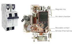
Klaus Tum: The main difference is that MCBs can be reset after they experience a fault (scenario) exceeding their trip parameters. Their trip mechanism consists of an electro-mechanical mechanism (a solenoid, which consists of a magnetic coil, housing and plunger/armature) that will react to the rapidly increasing current of a short circuit. The magnetic field in the magnetic coil will accelerate the armature in a way that it immediately hits the moveable contact of the MCB to break the circuit.
When it comes to slower increasing and smaller currents (overloads), the MCB employs a bimetallic strip that will bend according to the trip parameters and that will eventually hit the moveable contact on the other side of the pivot point to break the circuit. The arc (energy that consists of mostly fire) fault (especially when it comes to short circuits) will be guided into the so-called arc deion chamber and the arc will get extinguished there.
Fuses, on the other hand, need to be replaced every time they see a catastrophic fault. Fuses usually consist of a cylindrical (or sometimes) square ceramic (or sometimes glass) housing, filled with either sand or sometimes air (smaller fuses with lower amperage and voltage ratings) and conductive tips on both sides that are internally connected using a (specialty) wire that could be made of any kind of conductive metal such as copper, aluminum, alloys, etc. In case of a short circuit, the sand inside the fuse housing will suppress the energy of the fault, and the connecting wire will melt.
MD: What factors should be considered when selecting a miniature circuit breaker for a specific application of machine design?
KT: When selecting mini circuit breakers, the following factors should be considered:
- Amperage and voltage ratings needed for the panel/circuits
- Available short circuit current at the installation point and therefore needed kA rating of the MCB Trip curve to avoid nuisance tripping.
MD: Can you explain the importance of coordination between miniature circuit breakers and other protective devices in a machine’s electrical system?
KT: MCBs are usually employed “at the lower end” of the circuits, meaning closer or right upstream of the load. The reason for that is that they come in amperage ratings all the way down to 300 mA and can therefore be sized according to the full load amp (FLA) of the load better. Larger molded case circuit breakers (MCCBs) usually stop at 15 A and don’t go lower.
In addition, a smaller single load does not usually generate a high (short circuit) fault current and therefore the industry average of 10 kA short circuit interrupt capacity is usually sufficient. Therefore, MCBs protect mostly a single load and larger MCCBs protect a bank of smaller loads. The MCCBs need to be size (amperage rating, kA rating, etc.) so they don’t trip when only one of the downstream loads experience a fault condition. Taking care of that fault is the “job” of the MCB. In close cases, the trip curves of the different devices need also be considered (selective coordination).
MD: What are the main types of tripping mechanisms used in miniature circuit breakers, and when is each type typically employed?
KT: Thermal-magnetic trip mechanisms are the most widely used in MCCBs, all kinds of MCBs (tested to different UL standards such as UL 489, UL 508 and UL 1077). The main reason is that fault conditions “generate” heat and the MCB should react to that heat accordingly. The drawback is that the MCB will also react to heat or temperature that the environment around it (MCBs next to it, atmospheric temperature inside and outside of the panel installation) generates. These temperature effects can offset by properly sizing the MCB, utilizing cooling spacers (for cooling) between breakers or employing HVAC measures inside the panel.
Hydraulic-magnetic trip mechanisms are used in 3% to 5% of the MCBs on the market and are only provided by a few manufactures. It’s essentially the solenoid setup for the “magnetic” portion explained above housed in an oil filled chamber; or, in other words, they operate on the magnetic force produced by the load current flowing through a series connected solenoid coil, which is wound around a hermetically sealed tube containing an iron core, a spring and a dampening fluid.
The advantage of this kind of MCBs is that they can be used in hot and cold environments without the need of over or under sizing them. In addition, they don’t react to heat fluctuations. The big disadvantage of these MCBs is that they don’t (automatically) react to the heat the fault condition generates.
MD: How does the breaking capacity of a miniature circuit breaker impact its suitability for different machine design applications?
KT: The breaking (or interrupt) capacity of 10 kA (to maybe 14 kA, in some rare cases) limits the application of MCBs to smaller panels or downstream loads of larger panels (as described above).
About the Author
Sharon Spielman
Technical Editor, Machine Design
As Machine Design’s technical editor, Sharon Spielman produces content for the brand’s focus audience—design and multidisciplinary engineers. Her beat includes 3D printing/CAD; mechanical and motion systems, with an emphasis on pneumatics and linear motion; automation; robotics; and CNC machining.
Spielman has more than three decades of experience as a writer and editor for a range of B2B brands, including those that cover machine design; electrical design and manufacturing; interconnection technology; food and beverage manufacturing; process heating and cooling; finishing; and package converting.
Email: [email protected]
LinkedIn: @sharonspielman
Facebook: Machine Design
YouTube: @MachineDesign-EBM


