Push, Pull, Lift, or Rotate: There’s a Cylinder for That
Pneumatic cylinders are used to generate force and power linear motion on OEM equipment of all types. They can move product directly or move the components inside a machine that act on the product. They do this by pushing or pulling, lifting or lowering, rotating, or clamping. They can produce high force and a broad range of velocities, even stalling if needed without causing internal damage. They can be manufactured to tolerate adverse conditions and repetitive washdown. And they come in various designs to meet the requirements of different applications. What follows is a description the basic types and features of cylinders.
Cylinder Types
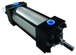
The original industrial cylinder, and still the most widely used today, consists of a tube or barrel—the cylinder—closed by sealed end pieces to form the envelope. Inside is a sealed piston. A rod attached to the piston extends through a sealed opening in one of the ends. The cylinder is mounted so it does not move and the load is connected to or contacted by the piston rod. A port at one end of the tube allows compressed air to act on one side of the piston, causing it and the piston rod to move. A port in the other end of the tube allows air from the opposite side of the piston to escape—usually into the atmosphere. When the roles of the two ports are reversed, the piston and rod stroke in the opposite direction.
This is a basic rod-style cylinder. As the name implies, it usually has a rod protruding from one or both ends. Other models have multiple rods passing through the same end to prevent piston rotation. Rod-style cylinders function in two ways: double-acting and single-acting. Both of these come in a variety of types, including repairable, disposable, compact, guided or bellows cylinders. There also are rodless pneumatic cylinders.
The basic rod-style cylinder remains the most widely used industrial cylinder today. (Photo © 2018 Bimba)
Double-acting cylinders use compressed air to power both the extension and retraction strokes, moving the cylinder back and forth. This arrangement makes them ideal for pushing and pulling loads within the same application. Superior speed control is possible with double-acting cylinders, achieved by controlling the rate at which air exhausts.
Single-acting cylinders accept compressed air on only one side of the piston. The volume on the other side of the piston is vented to atmosphere. Depending on whether it is routed to the cap end or rod end, the compressed air may extend or retract the piston rod. The most common type of single-acting cylinder is pressure-extended; an internal spring powers the return stroke after pressure is exhausted. In other designs, gravity or an external spring returns the piston to its original position.
Repairable cylinders can be disassembled to replace seals and other internal components. This procedure extends the cylinder's life cycle. These cylinders are generally robust in design and will be used in applications requiring heavier-duty components.
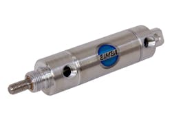
Non-repairable or sealed-for-life cylinders have end caps mechanically crimped to the tube. The piston is pre-greased before the cylinder is assembled. While they are less expensive to manufacture, they cannot be taken apart to repair without destroying the housing. These cylinders usually are used in lighter-duty applications and must be replaced when they reach the end of their life cycle.
Sealed-for-life cylinders usually are used in lighter-duty applications and simply replaced when they reach the end of their life cycle. (Photo © 2018 Bimba)
Compact cylinders are designed to fit into smaller spaces where only a short stroke is required. They are used in lighter-duty applications because they have a smaller bearing surface for the rod to ride against. They are mostly found in single-acting versions, but double-acting styles also are available.
Guided cylinders serve applications with significant side loads or those requiring that the load be guided (for example, down a conveyor). A dual-rod cylinder or a cylinder mounted to a guide block may be the solution.
With the addition of mechanical components, a cylinder’s linear motion can be converted to angular motion up to 360 deg. The rack-and-pinion rotary actuator with a rack turning a pinion gear and external shaft is often used in the process industry to operate quarter-turn valves. (Vane-type air motors drive other rotary actuators.) Sizing rotary actuators requires torque information about the load to be turned.
Bellows are durable, single-acting, collapsible actuators with flexible, reinforced elastomer walls and metal end plates. They extend when inflated and develop powerful strokes because of their large diameters. Their cylindrical configuration allows them to bend in any direction, making them useful where loads might vary in angle. Some application cautions: the maximum extension and compression of the bellows must be limited by external restraints. Unrestrained extension can blow off the end plate; exhaust without restraint can cause the load to crush the sidewalls.
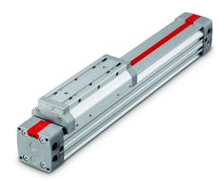
The rodless cylinder has no rod extending through its end caps. Instead, an external carriage slides back and forth on the tube’s surface. The load or tooling mounts on this carriage. An internal piston is mechanically connected to the carriage through a sealed longitudinal slot in the cylinder wall. Long sealing strips on the inside and outside of the cylinder tube prevent loss of air and ingress of dust. The slot is unsealed only between the lip seals on the piston as it moves back and forth.
Rodless cylinders move loads mounted on an external carriage. In this photo, the carriage is “externally guided”—partially wrapped around the cylinder tube for greater moment load capability. (Photo © 2018 Norgren, Inc.)
Rodless cylinders are used for long-stroke requirements and offer high moment loading capabilities for a variety of applications. This design saves space because the stroke is contained within the overall envelope of the cylinder. They are available with a variety of carriage designs. Three of the most common carriage options are internally guided, externally guided, and roller guided.
Features—a Basic Vocabulary
Cylinder type as described above is one selection criterion. Below are descriptions of other features to consider when deciding which cylinder to use. In the end, both cylinder and feature selection will depend on the precise application of the cylinder.
Bore size refers to the inside diameter of the cylinder tube or barrel measured in inches or millimeters. This key dimension is directly related to the force output capabilities of the cylinder.
Stroke length is the distance between full extension and full retraction of the piston rod—the distance from start to finish of its stroke. This, too, is conventionally measured in inches or millimeters.
Pressure rating is designated in pounds per square inch (psi). Most cylinders are designed to work at pressures below those typically produced by plant-air systems, but some applications may require higher pressure. The pressure actually supplied to a cylinder will normally be reduced through a pressure regulator to a level that will produce the desired thrust.
Piston rod diameter is dictated by bore size.
Port sizes and locations are also dictated by bore size but can be adjusted for custom designs.
Envelope dimensions. The National Fluid Power Association (NFPA) has established standards for many cylinder dimensions, making it possible to interchange cylinders from different manufacturers if replacement is necessary. Of course, there also are many models with unique dimensions—particularly if customization is required.
Mounting configuration refers to how the cylinder is attached to the adjacent equipment. The large number of standard mountings—both rigid and articulated—usually allows the cylinder to fit into movement criteria specific to an application. A variety of mounting hardware also is available.
Cylinder materials. The operating environment is the major factor that affects material choice. Typical material options for pneumatic cylinders include steel, aluminum, stainless steel, and composite. Some models are constructed of a combination of these materials.
Additional Options
In addition to the standard features described above, manufacturers offer a variety of optional features. For example, cylinder manufacturers use a variety of methods to seal the openings in the cylinder barrel and end cover of a cylinder. Designers have the option to specify alternative seal materials for applications that operate in extreme high or low ambient temperatures.
If the piston makes metal-to-metal contact with the end covers at the extreme ends of the strokes, the result will be excess noise and potential mechanical damage. Cushioning prevents such contact. Some cylinders have integral fixed cushions, a pre-engineered fixed cushion orifice that restricts the flow of exhaust air to slow the piston down at the end of stroke. This is beneficial because it prevents the cushion from being altered under field conditions: The amount of cushioning effect will not change and is repeatable.
Some cushion designs include an adjustment that can change the rate at which the trapped air escapes. This allows the machine operator to adjust the rate at which the cylinder is cushioned at the end of stroke. The latest is adaptive cushioning that automatically adapts to varying loads or to changes in applications without requiring the manual adjustment of the cushion screw.
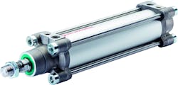
End-of-stroke cushioning prevents the noise and wear caused by metal-to-metal contact. This IMI Norgren ISOLine cylinder has adaptive cushioning that adapts to varying loads without requiring a manual adjustment. (Photo © 2018 Norgren, Inc.)
Non-cushioned cylinders are only suitable for full-stroke work at slow speeds that allow gentle contact at the ends of stroke. To operate non-cushioned cylinders at faster speeds, external stops with shock absorbers can be installed. These should be positioned to prevent internal contact between the piston and end covers.
Magnetic cylinders have a band of magnetic material around the circumference of the piston within a nonmagnetic cylinder barrel. The magnetic field can be imagined as a donut shape around the barrel. This shape travels with the piston as the piston rod strokes in and out. By placing reed switches on the outside of the barrel—one at each end, for example—signals will be generated each time the piston rod completes a stroke.
Configuring Multiple Cylinders
Multiple cylinders can be combined to create special force and/or stroke results. By mounting two or more cylinders end to end, they can be extended and/or retracted selectively to move an attached load reliably to a number of different positions. This is known as a multi-position arrangement.
The tandem (or multi-power) arrangement also joins two cylinders end to end, but in this case with a shared central end cover and a common piston rod. The combination then can double the pull and nearly double the thrust of a single cylinder of the same bore size. The tandem arrangement is suitable as an alternative to a larger bore cylinder when there is plenty of space available for length, but restricted width and height.
Things to Watch Out For
A very important general design consideration is to keep the cylinder thrust as close as possible to the centerline of the piston rod and free from misalignment or side thrust. Cylinders are normally intended to push and pull without excessive side load. Off-center thrust or side loads can substantially reduce the service life expected from the rod bearing and seals. Off-center thrust and side loading can be caused by improper mounting, cylinder deflection under load, machine frame deflection, and rod bending or sagging—as well as by poor design of the machine.
Sometimes this can be solved by increasing a cylinder’s bearing surface with the addition of an optional internal stop tube. A stop tube is a spacer placed between the piston and the rod end head. It increases the distance between the piston bearing and piston rod bearing when the rod is fully extended. This configuration is also helpful in applications calling for cylinders with very long strokes.
Rodless cylinders are a good option for handling applications that require side loading. They can carry loads above, below, or to the side; because there is no rod, there is no buckling or distortion. Rodless cylinders also save space because the stroke is contained within the cylinder body. With a rod-style design the stroke only begins at the point at which the rod leaves the cylinder, so the space required must include the length of the cylinder body and the length of the stroke. Rodless cylinders can deliver longer strokes, as well: up to 27 ft compared to 12 ft for a rod-style cylinder.
Most pneumatic cylinders are assembled with a coating of grease on the bore of the barrel and the seals for service with non-lubricated air. If the compressed air supply is clean and dry, the grease will give the seals a long life without adding oil through an airline lubricator. However, contaminated air will gradually compromise original grease lubricant and shorten the life of the seals. A lubricated air supply will extend the life of the cylinder, but it will also wash out the original lubrication. So once lubricated air is introduced, it must always be used, and the lubricator should be regularly checked and maintained.
A Clean Machine
One thing pneumatic cylinders have in common is tubing. After all, the compressed air has to get there somehow. Integrating the valve that controls the air and the cylinder itself in one package significantly reduces the amount of tubing required. It also allows machine designers to reduce the pneumatics footprint, reduce the energy required for compressed air, and build a cleaner, more-attractive-looking machine. Here are three examples.
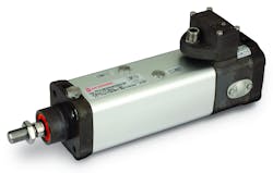
Using cylinders with an integrated valve and tubing, like this IMI Norgren IVAC, helps designers get a machine with a clean, streamlined look, as well as saving energy and installation time. (Photo © Norgren, Inc.)
Corrotec, Inc., Springfield, Ohio, a manufacturer of custom process systems for surface finishing, wanted to modularize the building and installing of their machines on customers’ sites. Distributor Mosier Fluid Power of Ohio recommended the IMI Norgren Integrated Valve and Actuator Control (IVAC). With just one airline from a distribution header and one cable from an I/O block, the IVAC saves Corrotec considerable installing time when compared with installing a traditional valve island and all the tubing on site.
In fact, the company found it can eliminate up to two days’ time from a typical installation. It also liked the sleek appearance of the cleanline IVAC. “We preferred the aesthetics of it, but more important for us was what it communicated about the quality of the whole system,” said Dan Edgington, a Corrotec project manager. “There’s a comfort factor for our customers who know that all the parts are sealed safely inside the package, especially in environments with a lot of dust and oil mist in the air.”
Presezzi Extrusion SpA, headquartered near Milan, Italy, thrives by building cutting-edge metal extrusion machines, including using the most cost effective and efficient pneumatic components. It was an early adopter of the IMI Norgren IVAC, as the modular motion-control unit combines the cylinder, pilot and control valves, position sensors, and speed regulators in a single integrated unit that fits in the same footprint as a standard actuator. Eliminating tubing between the valve and cylinder minimizes dead volume, reducing the cost of energy for compressed air by as much as 50%. It also reduces cost per stroke and speeds up response times.
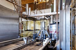
Mounting cleanline cylinders with integrated valves and controls on top of this keg racker and washer saves space and makes washdown easier. (Photo © Norgren, Inc.)
Left Hand Brewing Company, Longmont, Colo., needed new kegging equipment to handle rapidly growing demand for its popular stouts and ales. But the brewery’s space was so severely limited that the new kegging line would have to share space with a loading dock. Existing linear systems consumed more space than Left Hand could afford. It needed a system to clean and fill kegs that was compact and fast, and it also wanted to save on energy costs. And of course, the kegging line would have to meet beverage handling washdown requirements.
The solution was the Innokeg Till CombiKeg built by KHS, Dortmund, Germany. This unusual keg racker and washer uses a rotary design instead of a straight line, moving the kegs in a circle through the required stages of washing and filling. Installing multiple IMI Norgren IVACs on top of the machine makes this compact design possible, and with an ingress protection rating of IP67, the cleanline IVAC withstands the frequent washdowns required in this busy facility.
Putting it All Together
Pneumatic cylinders are the workhorses of industry, moving and positioning products or machine components that act on products. Pneumatic cylinders are simple and versatile components that have advanced over time to make more innovative machine designs possible. They are also part of an increasingly complex mix of products in today's industrial world. The development of cylinders with feedback capabilities and the use of programmable logic controls are just two examples. While a cylinder’s performance basics can be calculated, many external factors will affect its actual performance.
Putting together an actuator package that will meet the requirements of an OEM application can be daunting and time-consuming. Collaborating with a company that has pneumatic control experience plus a full product line can shorten the time to solution.
Sheila Campbell is a product marketing manager of Actuators at Norgren, Inc., an IMI Precision Engineering-branded company. For more information, please visit the company’s website.
