Engineering Essentials: A Closer Look at the I’s and O’s of VFDs
As variable frequency drives (VFDs) are becoming the primary go-to solution for motor control, their capability is not something that can be matched. With every new generation comes better performance, smaller size, and greater functionality.
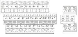
The image above is a terminal board diagram. Consult with the VFD user manual to find the function of the terminal.
In most cases though, VFDs are used for their variable speed control with minimal wiring terminations. But, is the product being fully utilized with all those empty terminals? Perhaps the function behind them and their potential is unknown. With all the possible wiring options and associated parameters, controls for a VFD can easily be troublesome. This article will address, in detail, the purpose and advantages of utilizing the inputs and outputs of a VFD.
Main Circuit Wiring
Of utmost importance is the main circuit wiring required to power the VFD and actually turn a motor. The input terminals accept line voltage and the output terminals connect the motor(s). Less commonly used, and sometimes even wired incorrectly, are the DC bus terminals. Generically labeled as positive (+) and negative (−) and in conjunction with the DC bus circuitry, components such as DC reactors, power regenerative units, and dynamic braking modules can be interfaced with the VFD using these terminals. Less-common uses include the addition of capacitance or common bussing, though special considerations need to be taken into account. Depending on the model and capacity of the VFD, a variation of DC bus terminals exist and therefore wiring will differ. Not all applications will utilize this circuitry, but it is extremely important these do not get confused with the input line or output motor terminals.
On the main circuit terminal block, the line, load, ground, and DC bus terminals will generally be located near one another.
Digital Inputs
The most frequently used and simplest way to remotely command a VFD to start a motor is with a digital input or DI. As the name implies, “digital” means either true or false (zero or one) and “input” is what the drive receives. Fortunately, most VFDs supply a voltage to their digital inputs (commonly 24 V dc), which will in turn allow the user to supply a dry contact such as a switch.
The VFD may also allow voltage to be sourced externally, though a setting change by means of a jumper or DIP switch may be required. Ranging anywhere from motor speed/direction change to external safeties, most DIs can be reprogrammed to any function available in the drive firmware. Certain model VFDs will hold unique functions of the Dis, with some even related to application-specific parameters.
Digital Outputs
Before the time of VFDs, panels consisting of motor starters, overloads, and relays dominated the motor control industry. While these controls were fairly simple, contacts and indicator lights may have been present to only provide a run and/or fault status of the motor. The digital outputs (DOs) on a VFD are essentially dry contacts which will not only provide a status, but can indicate an array of conditions dependent on the value of the assigned parameter.
Normally open, form A relays are the most common, though form C relays and/or photocoupler outputs exist on some models. Programming includes choosing both the function of the DO and the normal operating state (which may only be available in certain models). It is important however, that the current and voltage rating of the digital output are not exceeded as damage may occur to the internal circuitry. Whether using the DOs for indicator lights or other devices, their benefit and purpose is virtually limitless.
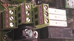
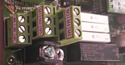
The digital output terminals may include Form A relays (White), Form C relays (Black), and their corresponding terminals.
Analog Inputs
At present, almost all VFDs have proportional-integral-derivative (PID) control built in. This is where an output value is calculated based on a feedback input and setpoint. It happens to be the analog input (AI) terminal in which the input source (feedback) is wired to. In VFD terminology, “analog input” refers to a varying current (mA) or voltage (DC) signal with upper and lower limits in which the drive is able to read and process. Most commonly, the analog input(s) is used to control output frequency to the motor, but many other functions can be assigned to it through programming.
Parameters adjustments also may include choosing between voltage or current input (a DIP switch may be required as well), and scaling if the actual input value differs from the rated value of the terminal. Lastly, a power supply such as 10 V or 24 V dc may also be available to use in conjunction with the AIs and an external device.
Analog Outputs
Have you ever wanted to monitor the current of the motor without looking at the keypad of the VFD? One way to do so is with a metering instrument connected to the analog output (AO) terminals. The analog outputs will source and provide either a current (mA) or voltage (DC) to an external device. Similar to the analog input, the actual signal of the AO is varied based on the assigned function and the scaling.
If desiring a 0-10 V dc signal based on motor current, for example, the VFD can output 10 V dc when the motor current reaches 100% and 0VDC when the VFD is stopped. The same holds true with a 4-20 mA output where 4 mA is 0% and 20 mA is 100%. Functions such as output frequency, motor current, transducer-based feedback, and many others can be monitored using the AOs. The applications and uses for them are practically endless.
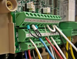
A combination of colored wires on a terminal board makes it easier to differentiate the function of the terminal being used.
Communications
Besides variable speed control, one of the primary features that make VFDs attractive is their capability for integration with many communication protocols. When online, a PLC (programmable logic controller) will constantly transmit and receive data to and from the VFD. Communication terminals exist either on the VFD itself or on an additional option board depending on the protocol desired.
In many cases, the PLC will act as the I/O for the system and command the VFD to run based on its internal logic. Besides wiring, parameter changes are generally required for setup and a DIP switch may act as an end-of-line resistor. While there are many advantages inherent to communications, additional cost, physical space, and system complexity need to be taken into consideration.
Other Terminals
The saying “every VFD is the same” is simply not true. For one thing, control terminals and their associated features vary from model to model. For example, a safe disable input (safe torque off) may only be available on industrial VFDs which are required to meet a specific standard. This input is hard-wired to the internal circuitry and will prevent the drive from running when a safety input is open or a jumper on the terminal board is missing.
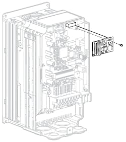
Another function only available on certain models is a pulse input. On this terminal, the VFD accepts a frequency range of DC voltage pulses that can be used for a variety of functions. Some models even have a pulse output that can be linked to a pulse input on another VFD. Lastly, a feature overlooked and sometimes forgotten is the option for expansive capability. Extra I/Os, encoder feedback, and certain communication protocols are all associated with additional circuit boards that connect to the VFD. Though not used in all applications, these options help expand the functionality of the VFD to meet the needs of the user and application.
Certain models have connection points where optional expansive I/O circuit boards can be added for additional capability.
As more people are reaping the benefits of variable frequency drives, they are slowly being integrated in almost every industry and application that uses a motor. It is imperative to understand the multitude of tasks a VFD can perform for equipment protection and to maximize efficiency. The inputs and outputs play a huge role in just that.
While at first glance, the 40-plus control terminals on a VFD may seem intimidating, they can pretty much be broken down into categories such as analog and digital or inputs and outputs. Having basic knowledge of the I/Os and their functionality is just the beginning to achieve that cost savings we’re all striving for.
Jonathan Kopczyk is a technical support engineer for Yaskawa, Inc.
