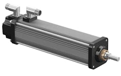
Engineering Refresher: The Basics and Benefits of Electromechanical Actuators
Download this article as a .PDF
Basics of Electromechanical Actuators
Electromechanical actuators are mechanical actuators where the control knob or handle has been replaced by an electric motor. The rotary motion of the motor is converted into linear displacement. The principle operation in most electromechanical actuators is based on the inclined plane concept. The threads of the lead screw are used as a ramp that converts the small rotational force by magnifying it over a long distance. This enables a large load to be moved over a small distance.
The simplified design of the motor motion is mechanically converted into linear displacement. Variations on electromechanical actuators have been devised to achieve higher mechanical efficiency, speed operation, and increase load capacity. Designs will differ from manufacturer to manufacturer, but in most designs the lead screw and the nut are incorporated into the motion.
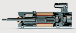
The Inmoco DA99 from Diakont is an example of linear roller screw actuator. The actuator is used in nuclear power plants worldwide, and delivers increased load capacity with greater reliability and a longer operational lifetime.
The common design of the traveling screw actuator is where the lead screw passes through the motor. The lead screw is fixed and non-rotating, making the only moving part the lead nut. It is rotated by the motor, and the lead screw can extend outbound or retract inwards. The motor moves up and down while the lead screw remains fixed. The motor is the only remaining rotating part.
There are different designs that have multiple starts with alternating threads on the same shaft. They start on the lead screw and provide a higher adjustment capability between the starts and the nut thread area of contact, influencing the extension speed and load capacity of the threads. The lead screw determines the direction of the motion of the nut, and linear displacement is attained by connecting the linkages to the nut.
In most cases, the screw is connected to a motor or manual control knob. Other designs use a ball screw and ball nut, or have the screw connected to the motor directly via gears. The gears help to transmit the low power motion at a high revolution per minute (RPM) through the gears to magnify its torque. This is done so it can handle the weight exerted on the screw, preventing the motor from engaging the heavy load directly.
This concept compromises linear actuator speed for attaining favorable actuator thrust, preventing the nut from moving with the screw head, and the non-rotating part is forced to interlock with the actuator. It is common for a worm gear to be used, as it allows for a smaller built-in dimension while allowing for greater travel length.
There are different types of travel within the actuator. As mentioned earlier, a traveling-nut linear actuator has a motor that stays attached to one end of the lead screw. It is either parallel or perpendicular to the actuator, perhaps indirectly through a gearbox. The motor rotates the lead screw and the lead nut is retained so it does not rotate. In this setup, the nut travels up and down the lead screw.
A traveling-screw linear actuator configuration is different as it has a lead screw that passes entirely through the motor. The motor essentially crawls up and down the lead screw that is prohibited from rotating. The only rotating parts the inside the motor, with the moving parts not being visible from the exterior.
Several types of motors can be used for an electromechanical actuator: dc brush, dc brushless, stepper, or even induction motors. The motor used is based on the application requirements and the loads the actuator is expected to move. An actuator using an ac induction motor for example, will be used to operate a large valve in a refinery process. This is because accuracy and high resolution are not the priority—rather, high force and speed are.
With actuators used in a lab setting (such as for robotic instrumentation, laser equipment, or X-Y tables), finer resolution and high accuracy are required. In this case a fractional horsepower stepper motor with a fine pitch lead screw will be used.
Benefits of Electromechanical Actuators
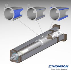
The image above from Thomson Industries is a cross section of an electromechanical actuator. Inside the actuator, side loads are handled by maximizing the surface area. By increasing the surface area, lateral loads are supported and helps reduce play in thrust situations.
According to Niklas Sjöström, product line manager, Systems Group, at Thomson Industries Inc., the desire for electromechanical actuators has increased in recent years. A few of the goals that have influenced the industry are:
- Improving machine performance with electromechanical actuators capable of higher precision.
- Reducing the size of equipment with electromechanical actuators that require only about a quarter of the space to deliver the same thrust as pneumatic actuators.
- Utilizing energy more efficiently, because electromechanical actuators do not need air compressors running 24/7 maintaining pressure.
- Reducing maintenance and total cost of ownership, because electromechanical actuators use fewer components, do not require compressors, and do not suffer air leaks.
It is common to compare electromechanical actuators against hydraulic or pneumatic actuators. Typically, pneumatic actuators have been used for light loads and only for travel between two positions. Each end of the travel is controlled by mechanical limits or hard stops. At these conditions, since control is not required at either end position, pneumatic actuators travel at a high speed and are inexpensive. It is possible to achieve more accurate control using pneumatics if proportional regulators and valves are implemented.
However, the consequence is a higher costing and complex system. Maintenance of the system also becomes more expensive. Also, maintaining control of the actuators while at the same time keeping the air compressed has its limitations. To apply the constant pressure, the compressor must be running continuously. Pneumatic actuators have problems providing slow and controlled speeds.
Hydraulic actuators are typically used for high-force applications, producing forces 25 times greater than that of an equal size pneumatic cylinder. Using fluid power, a constant pressure can be held without having to apply additional amounts of energy. Hydraulic actuators, just like pneumatic actuators, have motion profiles which are difficult and costly to control. With hydraulic actuators, oil leakage and disposal are persistent problems. Both pneumatic and hydraulic systems have issues due to impurities in their pressure and return lines.
The major benefit of electromechanical actuators is that engineers have complete control over the motion profile. They are equipped with encoders that can be used to accurately control velocity and position. Some of them provide the ability to control and monitor torque and, as a result, the amount of applied force. Electromechanical actuation systems can be reconfigured and programmed without having to be shut down, which means the force and motion profile can be modified with software while the device is running.
Electromechanical actuators offer significant cost savings because they only consume power when they are performing work. To maintain a position, the system stays in place while idle. The average efficiency of a ball and roller screw actuator is around 90%. Their high efficiencies, low maintenance, and increased up time also help to reduce operating costs. They are also environmentally friendly since they do not require hydraulic fluid. This makes them ideal in hazardous areas.
For engineers, electromechanical actuators can simplify the design process since they are easier to specify and design. There are only three steps required to determine the necessary size of an actuator: determining the duty cycles, calculating the load requirements, and specifying the stroke and retract length.
Electromechanical Actuators in the Field
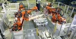
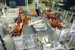
The Kuka robots are performing a welding operation with robotic weld guns. They are using electromechanical actuation to perform the various welds need on the car chassis.
Different industries are starting to find areas in their process where an electromechanical actuator can be used. Industries like packaging, food, energy, process control, construction, and the automotive industry have started to turn towards electromechanical actuation systems.
An example from Motion Control Online, part of the Motion Control & Motor Association, analyzed how the automotive industry has started to use robotic weld guns powered by electromechanical systems. Before, the weld gun operations were operated via air or fluid power systems but suffered from inefficiencies and were difficult to control. Using electromechanical systems have offered a greater range of control and efficiency.
The primary application for robotic weld guns is in spot welding of stamped sheet metal parts to form the car chassis. These operations require high accuracy and consistency due to the high number of welds used in the car chassis. This work is repetitive in nature, which is the reason it is an automated process. The weld gun sits at the end of the robot arm and is required to reach specific positions of the parts of the car chassis.
Now, the robots that control the movement have been driven by electric servo motors, but the weld gun actuators have typically used servo-pneumatic actuators driven by pneumatic cylinders. This offered manufactures the benefit of a simply design and low acquisition cost. The tradeoff, though, is a system that is at times hard to control and inefficient.
The most commonly found electromechanical actuator found in heavy industries, such as automotive manufacturing, is the rotary servo motor coupled with a rotary-to-linear mechanical transmission. It can be found in either a ball screw or roller screw configuration. Roller screws are the preferred option, since they offer 5 to 15 times the lifespan when compared to a ball screw. Three main advantages of a roller screw over a ball screw are:
- More contact points, which means the friction force can be evenly spread out against a bigger surface. The overall friction is less and the life of the actuator is increased.
- Rollers are synchronized when connected to the nut with the screw, allowing for higher rotational and linear speeds.
- Rollers circulate in a synchronized motion around the roller screw, which results in less vibration and noise.
The Exlar GSX-Series roller screw actuator combines both the mechanics of the screw and a servo motor in one unit. The traditional roller screw design is converted into an inverted design. The roller screw nut runs in a ground hollow shaft that is used as the rotor of the servo motor with shaped neodymium iron boron magnets bonded on.
There are different types of configurations of the roller screw actuator. The motor can either be external or ones where the motor and roller screw are integrated into one unit. In the second configuration, coupling the motor directly with actuator eliminates the backlash resulting in higher dynamic response and better performance.
Using an electromechanical roller screw actuator in place of pneumatic actuators for robotic weld guns offer significant benefits. First, the life expectation of the actuator increases. Roller actuators offer higher load capacities; hence they deliver advantages in working life. The relative travel life for a roller screw for a 2000lbf /8900N load application will have an expected service life that is 15 times greater.
Second, the actuators can maintain a tight force repeatability. For example, a roller actuator can a hold a force repeatability of 50 Newtons within its nominal welding force. Lastly, the energy savings when using electromechanical actuators are high. According to 2011 study at the University of Kassel in Germany, it is possible to have 90% of savings when compared to fluid power. A hydraulic actuator operating under the same load and duty cycle conditions, would require 4.4 times more energy and a pneumatic cylinder 10 times more energy than the electromechanical actuator.
With these benefits, it’s easy to see how electromechanical actuation offers many industrial areas an alternative for their actuation systems.
