Design Essentials: Synchronize Position and Force with an Electro-Hydraulic Motion Controller
Download this article as a .PDF
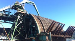
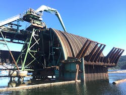
Hydraulics is great for lifting heavy loads and applying large amounts of force, but the same power that is required to exert a large amount of lifting or compression force can also do damage or produce waste if not controlled. A sawmill in British Columbia used a pair of 31-ft.-long hydraulic cylinders to operate a carriage that lifts log bundles into the mill (Fig. 1), but the lifting carriage occasionally sustained damage by the hydraulic cylinders moving at different rates of speed.
1. The arms that lift bundles of logs out of the bay and into the sawmill is operated by two 31-in.-long hydraulic cylinders.
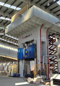
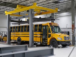
In China, a 3,000-ton automotive body panel press (Fig. 2) failed to reliably keep the platen level during a compression cycle. In Indiana, a vehicle roof-crush test system (Fig. 3) needed to exert a precisely executed and documented amount of force up to 100 tons on a vehicle roof as large as that of a school bus in order to meet industry safety specifications.
2. The platen in the automotive panel press must remain level even as up to 3,000 tons of force are being applied.
3. The vehicle roof-crush test system is operated by four hydraulic cylinders at the corners that must apply up to 100 tons of synchronized target force.
What’s the common problem that design engineers needed to deal with in each of these applications? It is the precise synchronization of multiple hydraulic axes. In a machine whose functionality depends on coordinated motion, the lack of synchronization can damage the machine or damage the machine’s output, or both.
The Solution: Synchronization
Each of the above applications used multi-axis synchronization to improve the productivity and quality of output and/or reduce maintenance problems compared to using older hydraulic technologies.
To improve the reliability of the log lifting operation, the sawmill managers upgraded the motion control system operating the arms. To fix the potential platen skewing problem, the automotive press manufacturer added cushioning cylinders at the four corners of the platen to ensure that it remained level during a compression stroke. And to control the vehicle roof crush test system, the design engineers in that company set up a test rig with four hydraulic cylinders working together to apply a tightly controlled amount of force.
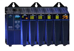
4. The RMC200 from Delta Computer Systems Inc. can control up to 32 motion axes simultaneously, plus it can serve as a data acquisition subsystem in test applications. A built-in Ethernet interface is provided for downloading motion programs or uploading motion status or test data from registers inside the controller.
All of these design teams added a new motion controller to their systems, a controller with special support for closed-loop control with the ability to link the motion of multiple axes. Figure 4 shows a motion controller with special capabilities for synchronization and controlling both position and force in hydraulic systems.
Selecting the Right Transducers
Precise closed-loop control requires precise feedback. Cylinder position information for all three of the applications discussed here comes from linear magnetostrictive displacement transducers (LMDTs). Typically mounted in the cylinder itself, LMDTs are useful because they provide precise position measurements and don’t require adjustment or homing steps at machine startup.
Pressure or force information is typically provided by load cells mounted at the end of the piston rod, or pressure transducers mounted in the cylinder on either side of the piston. In the event that pressure transducers are used, force applied by the cylinder can be calculated by computing the pressure difference between the sensors.
The usual thought when designing a motion control system is that one needs transducers that offer just a little more resolution than what is required by the application’s positioning or pressure requirements. This view may be correct for relatively simple applications involving continuous or start/stop motion, but it is often not true for those involving dynamic conditions. The need for finer resolution increases for applications requiring that accurate velocity or acceleration measurements be factored into the control algorithm. In synchronization or gearing applications—where the motion of a slave axis is proportionally related to that of a master axis—the master axis feedback should have as much resolution and accuracy as possible so the slave axis (or axes) can follow a smooth motion profile. Applications that move very slowly also need high-resolution feedback so that the motion controller can detect changes in position or force each time the control loop is executed.
Selecting/Sizing Cylinders and Valves
No matter how much attention is given to motion controller selection and programming, fluid power system performance may be limited due to incorrect sizing or physical location of fluid power system components. For actuators moving moderate to heavy masses, the acceleration, velocity, and deceleration are limited by the available force—not by oil flow. Since cylinder size determines the force that an actuator can produce, if the cylinder diameter is too small, the actuator may not be capable of attaining the desired speeds or cycle times required by the application.
Choosing the size (flow rating) of the valves is relatively easy once the correct size of the cylinder is identified. Servo-quality valves should always be used because they provide an infinitely variable flow of hydraulic fluid, and typically have a faster and more linear response than other proportional valves. Linear valves with a fast response are necessary for high-performance position/pressure control systems.
Old two-position “bang-bang” valves are not suitable for closed-loop control. They cause hydraulic shock and vibration, which results in machine maintenance problems. Of course, no valves perform perfectly, and a good motion controller is still required to compensate for the valve response and the mass and spring effect of the actuator and load.
5. Each leveling cylinder is instrumented with a linear magnetostrictive displacement transducer (LMDT) to provide position feedback. Pressure sensors in the cylinders mounted on each side of the piston produce data which are differentiated to provide force feedback.
Figure 5 shows the hydraulic system block diagram for the four platen-leveling cylinders in the automotive panel press. The transducer and valve connections to the motion controller are clearly visible.
Motion Programming Techniques: Virtual Gearing
The key to motion controller programming is setting up a connection and relationship between the control loops of the axes to be synchronized. Some multi-axis motion controllers have built-in functions that support synchronization.
The vehicle roof crush test application uses four hydraulic actuators (cylinders), mounted at the four corners of a heavy-gauge pressure plate and controlled as four separate motion axes. System design engineers used a special function of the motion controller called “virtual gearing” to cause all four axes to move in precise synchrony to ensure that the pressure plate is kept completely level during a compression operation.
The four “slave” axes follow a virtual “master” axis, which is set up to control the position of the pressure plate and the cumulative force being applied. The motion controller tracks the position of each corner cylinder using inputs from an LMDT attached to the cylinder, and controls the compression force using a load cell mounted on each cylinder rod end.
Motion Programming Techniques: Cascaded Control Loops
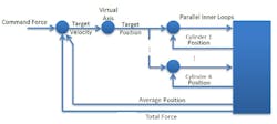
The motion controller in the automotive panel press performs its control functions using a “cascaded-loop” architecture. An inner control loop works to level the platen, while the outer loop simultaneously adjusts the target positions of the cushion (leveling) cylinders to follow the motion of the platen. The outer control loop also monitors the force exerted by the cushioning cylinders to make sure that it remains under the limit provided by a supervisory PLC. If the cumulative force is too high, the motion controller will change the position of the platen to maintain the force below the set limit.
6. Cascaded control loop diagram showing how the motion controller in the automotive panel press works to keep the platen level while it follows the motion of the platen and monitors the force exerted.
The cascaded control architecture is shown in Fig. 6. To level the platen, the motion controller computes the average position of the cushion cylinders, which it treats as a virtual master axis position, and works to move each cylinder position to match this average. To calculate the force being applied by each cushion cylinder, the motion controller computes the difference between the hydraulic fluid pressure on each side of the piston.
Motion Programming Techniques: Custom Feedback
In the automotive press application, mathematical computations are done by the motion controller on the raw feedback from the position and pressure transducers using a feature called “custom feedback.” Custom feedback refers to the ability of the motion controller to do mathematical or logical pre-processing of the raw feedback sensor data before the resulting value is provided to the control loop algorithm. By doing math on the raw data before that feedback is used by the control loop, the control algorithm itself can be much more straightforward and simpler to implement and tune.
Motion Programming Techniques: Position-Pressure/Force Control
Both the automotive panel press and the vehicle roof crush test application take advantage of the motion controller’s ability to control based on force, as well as position, and to smoothly transition between the two. The outer loop of the press starts in position control, monitors the total force applied by the main cylinders, and transitions to force control when the force reaches a certain value—all while the inner loops are controlling position.
The vehicle test system similarly starts in position control, then applies a controlled force when commanded. The bundle lift system just monitors the force now; force control may be implemented as feature later.
Developing/Tuning the Application
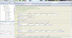
Programming the motion steps is typically done using development software provided by the motion controller vendor. While some motion controllers need to be programmed by low-level machine instructions similar to those used with a general-purpose computer, others have graphical programming tools available that can set up motion algorithms, including axis synchronization relationships using drop-down menus.
7. Delta Computer Systems’ RMCTools software lets designers build motion programs using drop-down menus to select motion parameters.
The screen in Fig. 7 shows how programming the operation of the four corner cylinders in the roof crush test application is done by filling in boxes and selecting options from pull-down menus. As the figure shows, the velocity, acceleration and deceleration rates can be set to cause the axes to start, stop, and move smoothly.
Following programming, all motion systems need to be tuned. In the case of the vehicle roof crush tester, the test rig initially shook. Then the system designers used the motion controller vendor’s automated tuning tools to stop the vibrations and get the system pretty close to the desired motion profile. After that, the team did fine-tuning, operating the press plate up and down at various speeds, and by testing different vehicle cabs with different amounts of crushing force.
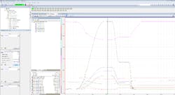
The fine-tuning process is made easier if the motion controller vendor provides a graphical motion plotting tool. See Fig. 8 below for an example.
8. In the vehicle roof crush test system, the RMCTools Plot Manager from Delta Computer Systems Inc. enables the test operator to visually track the values of all transducers and the values of the geared axis parameters during a test.
As the design teams discussed in this article have found, with synchronized motion control set up and tuned correctly, system motion is made smooth, machine productivity is increased, and waste and machine maintenance costs are decreased.
