At Solidworks World 2018, the power of design and fabrication is a cornerstone to the company’s motto. With every new update, it brings new tools to machinists and manufacturers to ensure they have accurate production parts. In one of its product showcases, Solidworks setup a mini machine shop creating from start to finish shifter arms for a vehicle. The showcase highlights how a designer can use Solidworks CAM to take their part from the mill all the way to inspection and engraving.
The 3D Solidworks Model
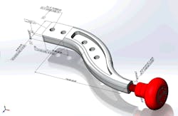
The process starts with the modeling. By using Solidworks, engineers create a 3D representation of the shifter arm. This model is created with all the features, tolerances, and production information it needs to be sent out to the different milling processes. The more detailed an engineer can be in a model-based definition, the easier the production process will be.
Zone #1: 2D Cutting
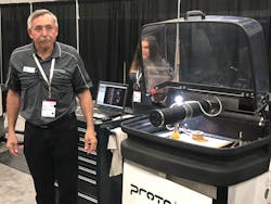
The first step prior to milling is to cut out the 2D profile. The OMAX protoMAX waterjet cutter is responsible for cutting out the profile on the arm component of the shifter arm assembly. The cutting process starts with a flat plate of material. Once the part is programmed, the protoMAX cuts the profile out of the blank metal stock. After the process is completed, the part is sent to the mill to remove the piece from the blank.
Zone #2: 3+2 Milling
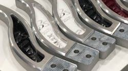
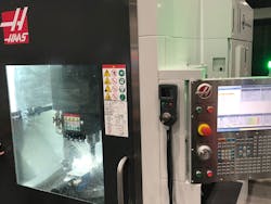
The Haas UMC 750 is responsible for milling the arm component of the shifter arm assembly. The process starts by milling from the 2D profile completed in Zone #1. The part is programmed into the UMC 750 and creates the necessary steps to mill out the arm. The mill uses water to make the machining process easy and smooth. Once the milling is done, the part is ready for quality inspection.
Zone #3: Turning
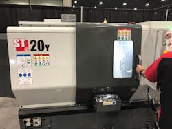
The Haas ST20 is responsible for the knob component of the shifter arm. Like the UMC 750, the process starts with a piece of round stock, cut to a specific length. After the part is programmed into the ST20, the necessary steps are generated to create the knob. The ST20 mills the entire knob and leaves only the engraving step for further down the production line.
Zone #4: Inspection
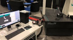
Once all the parts have completed their machining processes, they are brought over to the inspection zone. There the Solidworks Inspection and Origin Checkmate software are used to verify the part. The manufactured components are measured and compared to the original Solidworks model. By using the model-based definition, the inspection equipment is programmed to check tolerances, clearances, fits, and the overall build of the part.
Zone #5: Engraving
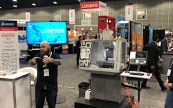
The last step of the process is to engrave the knob of the shifter arm. The Tormach 440 is responsible for the engraving. The knob that was milled in zone 3 with the Haas ST20 is now brought over to the Tormach 440. Here the knob is engraved and the production processes finalized. The knob can now be brought over for quality inspection and final assembly.
The Assembled Shifter Arm
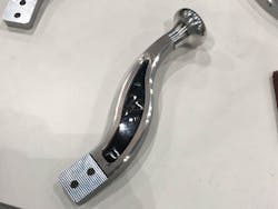
The shifter arm is finally assembled and ready to ship. The Solidworks CAM and Inspection software allow for easy translation from the computer design model into the machining process. This is just an example of how Solidworks looks to empower its users with a straightforward process for fabricating their creations.
