Tips on Designing Printed Circuit Boards for Motion Control
The days of “electro” and “mechanical” being separate disciplines are long gone. Virtually all mechanical systems now come with some form of electronics for monitoring, control, or both. Electronic printed circuit boards (PCBs) show up just about everywhere. PCBs are made up of a fiberglass-like substrate, with multiple layers of copper traces running between connections on various electronic components, with the components soldered onto the top and/or bottom side of the board. These PCBs will be used in your motion-control systems to send commands, collect data, provide real-time monitoring, and set limits and safeguards.
The process of designing those PCBs is, in many ways, not that different from mechanical design, with some key differences. As with mechanical devices, PCB design entails the use of computer-aided design (CAD) software to create a finished product out of a set of components.
With PCB CAD, the first step is called “schematic design.” It involves taking schematic symbols —line-art versions of components that show the electrical workings and connections, but not the mechanical packaging—and drawing wires (called nets) between all of the various component connections to create a working circuit.
The next step, called “layout,” is just as important as schematic design, but often regarded as little more than an afterthought. The layout portion of PCB design again uses CAD software. In the layout phase, the PCB size is defined, all of the components are positioned based on their mechanical footprint, and those wires drawn in the schematic design phase are routed in what will become the physical copper traces on the finished circuit board.
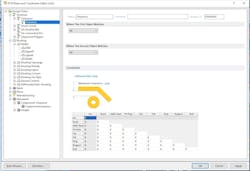
This is an example of how to set design rules in PCB CAD software like Altium Circuitmaker.
However, it is not as easy as it sounds. Many of those copper traces need to do different jobs. Some carry a lot of current or voltage, while some carry low-current high-frequency signals. In mechanical design, fasteners are a decent analogy to the copper circuit traces, and come in a multitude of sizes and grades. In PCB design, copper is just copper, but it can be put down in different widths on the PCB, based on design rules.
Design rules set in your PCB CAD software will do one or more of two things.
- They set the limits of the capabilities of the PCB fabrication company you will use to make your blank PC boards. For example, if your fab house has a minimum trace and space (between traces) of 5,000th of an inch (5 mm), your design rules and a design-rule check will ensure that none of your traces or spaces are too small for their processes.
- They can be used for rules-based design. Some software will automatically size traces based on the design rules you set ahead of time. With this type of software, if you want all of your power and ground traces to be 16 mm, you set a net class with a width of 16 mm, and assign the power and ground nets to that net class. The software would automatically make any power and ground nets 16 mm wide.
Your design rules will be a crossover between what you need and what your fab house can produce. Some more primitive CAD software will require that you manually pick the width for a via or copper trace if you want it to differ from the default. Other software, as noted above, will let you set up a series of design rules, and will pick widths based on those rules.
The Guitar is a PCB mounted servo drive from Elmo Motion Control. It provides top servo performance, networking, and intelligence capabilities within a high level programming environment. The Guitar features sinusoidal full vector control as well as trapezoidal and DC motor commutation methods. PCB mounted servo drives like this one offer a combination of the PCB mountability, high power capabilities, rich motion features, programming flexibility, a wide variety of feedbacks and CANopen networking.
For example, you might specify that power and ground traces are 16 mils in width and standard signal traces are 8 mm wide. The CAD system would then default to those widths when you picked a net in that net class. The net is the connection, like from pin seven of chip U2, to pin one of diode D3. The net class would be the type of net, like power or ground, or signal.
You will need to refer to your fab house, both to ensure that they can build what you need, and to get the final say on their design rules. Some fab houses, such as Sunstone Circuits, even have downloadable design rules for various CAD packages. That makes setting things up a lot easier.
About the Author
Duane Benson
Chief Technology Champion
Duane Benson is the Chief Technology Champion at Screaming Circuits, a prototype PCB assembly electronic manufacturing company in Canby, Ore.


