Download this article as a .PDF
When designing an experiment or test, simplicity is important. Each process added to a test or experiment to obtain data increases the potential for error. For destructive testing or experiments, getting as much information out of a sample is desirable to limit the amount of parts needed. Hooke’s Law has been around since 1678. It defined the relationship between stress put on a material and the resulting deformation. This article will cover the past, present, and future technology that has been used to measure this law.
Past
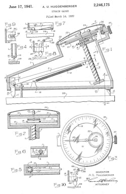
Mechanical strain gauges: Like many early designs, the first strain gauges were analog. Mechanical devices like springs and levers are still used today, but these early models weren’t very accurate. The force needed to cause a shift in the measurement—often called force of shift—tended to be high. One example to lower the force to displace an indicator was filed on March 14th 1939. The A.U. Huggenberger Strain gauge was to provide an improved extensometer that worked in one continuous operation. The goal of the inventor, Arnold Huggenberger, was to keep the force of shift as small as possible to improve the device’s accuracy and sensitivity.
These devices had some disadvantages. For one, they needed to be clamped firmly so the device didn’t move, causing an inaccurate reading. Charles Wheatstone published the effect of resistance in an electrical conductor due to mechanical stress in 1843. Measuring the electrical resistance was clearly advantageous to these mechanical methods, but wasn’t used.
It took almost 80 years for the technology to become cost effective. In 1938 Arthur Ruge from MIT invented his strain gauge to help a graduate student complete investigation into earthquake stress in elevated water tanks. This is similar to the strain gauges used today.
Present
Resistive: To make the first resistive strain gauge, Ruge used highly resistant filament in a zigzag pattern. Metal foil is now most commonly used. Foil resistive gauges are sensitive, accurate, easier to produce, and use less material. However, foil can only elongate so far, and this type of strain gauge doesn’t work well for ductile materials.
Conductive material can be added to elastomers for a stretchier gauge. When there are elastomer dielectric layers between electrodes filled with conducting particles, you get a capacitive elastomer sensor. Flexible resistive gauges will have a non-linear measurement where the capacitive sensor will be near linear.
|
Advantages |
|
|
Resistive Strain Gauge |
Capacitive Sensor |
|
Robust—resistant to shock, vibration, dynamic pressure changes |
Better for handling over pressurization |
|
Cost-effectiveness and ease of manufacturing |
Sensitivity—lower range capabilities |
|
Temperature compensation |
Better creep, linearity, hysteresis, and repeatability properties |
While these difference matter, we must go back to the first point: getting the most data from the least amount of energy. In the aerospace industry, monitoring strain on components like wings is important. “A material experiences fatigue after it is subjected to repeated loading and unloading,” said Michael Heflin, CEO for Sensuron. “An estimated 90% of structural failures that occur in all industries are a result of fatigue. Many engineers use a strain-controlled testing method that uses cyclic loading to predict the life of an application under fluctuating loads.
“The objective of a fatigue test is to determine the life and breaking point of a structure or component—i.e., the location of and number of cycles until failure when a material is subjected to a sequence of stresses,” he continued. “A number of methods are used to obtain stress and strain data, including strain gauges. The lifecycle of strain gauges themselves decreases dramatically as strains reach values of 2,000-4,000 µ-strain. This means that strain gauges are unable to accurately assess fatigue over certain parameters and long periods of time.”
Using Von Mises criterion and, more recently, computer-aided drafting with finite-element-analysis (FEA) software, engineers can predict stresses and strains between strain gauges. Although FEA offers accurate calculations on a wide array of materials properties with simulations, some applications require more data. Aerospace engineers, for example, rigorously test designs and materials. In one case, Boeing tested the wing box for the 787 using more than 1,700 strain gauges, which are still connected and wired manually (the wing box connects the wing to the fuselage and supports other subsystems, such as the landing gear). Testing for the wing box required hooking up in excess of 3,400 wires, which increased time spent, weight, and cost.
NASA might have found a better solution decades ago: fiber Bragg gratings (FBG). After a lot of research and a need for more information, FBG technology was able to yield 1,400 points of data along the distance of a fiber.
Like the delay in resistance strain gauges, FBG is still catching on. The price and lack of awareness slowed mass market adoption. Over the next five years the cost is anticipated to reduce by 20% to 30%, which will open up new opportunities in the automotive, medical, aerospace, and energy markets.
Companies that make FBG strain gauges are working with universities to teach students how to use this technology, which has many potential applications. For example, aerospace engineers could use it to determine wing loading while also providing accurate fuel readings. Automotive designers can determine maintenance and operational lives of vehicles. Civil engineers could monitor infrastructure “health” with the sensors. Overall, by embedding these fibers into products, it can save the time, money, and, weight associated with traditional strain gauges and other sensors.
Limiting factors affect the operating temperature and strain range of fiber-optic sensors. “It is the fiber that typically limits these ranges,” said Alex Tongue, applications engineer for Sensuron. “For example, different types of coatings can be used on a fiber-optic sensor to monitor different temperature ranges. Fiber sensors can have operational ranges of –422° to 1,292°F, depending on the coating and type of fiber.
“Individual applications typically do not require this range, so most sensors fall somewhere in the middle,” Tongue continued. “Sensuron usually uses fibers that operate from –422° to 599°F.”
Having thousands of accurate strain measurements from a single fiber that’s about the diameter of a human hair in real time at the speed of light is hard to compete with. As the cost is reduced and more companies developed platforms that can handle the mass of data a system a FBG system will produce, it may change the way engineers think about testing.
Future
Having developed FBG technology, in 2014 NASA did a test flight on what might be the future of aviation. A wing cuts through the air, but what if it could dynamically adjust to it instead? NASA’s Green Aviation project successfully tested a wing that does this.
Called the Spanwise Adaptive Wing (SAW), it is able to move up or down by about 15 deg. Wing articulation was examined in the XB-70 Valkyrie about 50 years ago. Actuator technology has since improved and the amount of drag reduction and increase in performance is now making it feasible.
Keeping track of the strain along a wing is important. Keeping track of strain is even more important if that wing is dynamic and articulating to the air around it. Traditional strain gauges can only indicate a single point and must be wired. Fiber Bragg grating (FBG) strain gauges are about the size of a hair, and a single fiber can produce real-time strain readings for multiple points along a surface, making it advantageous for this application.
In addition, FBG can detect strain from –18,000 to 18,000 µε (micro-strain). The range depends on the laser used and type of fiber. Some sensors set the strain range using software. Table 1 shows a comparison between fiber optic sensing technology and resistive strain gauges.


