Maximize Laser-Micromachining Performance with Motion Control
Download this article in PDF format.
Motion-control systems provide greater control and accuracy for production. Laser-micromachining processes are useful when developing a prototype part. Once it comes time to mass-produce a product, the integration of human-machine interfaces paired with motion-control devices like servos help ensure accuracy and repeatability. Let’s review some basics of laser micromachining and then dive into how motion-control systems can improve the process.
Basics of Laser Micromachining
Laser micromachining defines the process of using pulsed lasers to create small design features in parts that are micrometers or millimeters in length. The pulsed lasers deposit small, finite amounts of energy into the material, resulting in precise and reproducible material removal. The deposition of energy allows the laser to ablate, cute, drill, machine, or scribe in the material. The two most common processes are laser drilling and laser micro milling.
Laser micro drilling creates holes that are essential design features for products. These features could be holes for wafers, medical cannulae, or micro channels for fluids. An example would be drilling a hole into a stainless-steel part. The hole must be carefully drilled for the precise flow application. The hole requires a smooth wall without any burring of edges. The material thickness is 0.01 inches and the desired diameter size of the finished hole is 0.0008 inches with a tolerance of ±0.0005 inches. In Figure 1, the steps detail how that would be accomplished via laser micro drilling.
1. The steps above highlight how to drill a hole using laser drilling. Careful steps are necessary to ensure the hole be exact and maintain its tight tolerances. (Courtesy of Amada Miyachi America)
The drilling for the process in Fig. 1 was so exact that the last step was not required. The long pulse duration creates a melt pool. This melt pool is ejected, and due to large amount of heat deposited into the part, a large heat zone is created, which results in the melted region. The short pulse duration has the opposite effect, creating a smaller melt pool that results in a fine expulsion of material; it also cleans the outside edge of the hole.
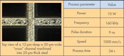
Micro milling involves the removal of material to a specified depth. This creates relief features such as grooves, slots, and profiles, without having to cutout through the material. It is a frequently used technique for industries involved with medical and electronic devices. The application example in Figure 2 is for a cross-machined channel into a thin sheet of stainless steel. The thickness is 0.001 inches and the machining depth required is 0.0005 inches without breaking the backside. Fig. 2 lists the steps involved in the process.
2. The cross channel was machined using laser micromachining, which prevents the channel from penetrating through the material but provides necessary relief to the part. (Courtesy of Amada Miyachi America)
Short pulse duration was critical to achieve the exact shallow depth. The short pulse duration creates a shallow melt pool and is then extracted, removing very fine layers of material.
Depending on the lasing medium, the laser is classified into two types: gas or solid. The gas classifications breakdown into three types: helium and neon, argon, and CO2. Solid lasers also breakdown into three types: Nd-YAG, Nd-glass, and ruby-alumina. Common polymers used in laser micromachining include Kapton, Cirlex, PEEK, polystyrene, PMMA, polycarbonate, PTFE, and Mylar. And the metals most commonly used are stainless steel, copper, nitinol (nickel titanium), tantalum, gold, and aluminum. The proper laser source will depend on the material type.
Matching the low transmission point of a material to the corresponding laser wavelength will achieve the best results. For metal machining, gas or fluid assist is often used to improve the cut quality, expel the molten metal, and minimize the heat affect zone. Infrared lasers are usually the first choice based on quality and cost. However, when a feature is less than 10 microns, ultraviolet lasers are good alternative, assuming a thickness of 0.003 inches.
Improving the Process with Motion Control
To ensure accuracy and repeatability in a laser-micromachining process, it is common to use motion-control systems. Customizable human-machine-interface (HMI) development platforms offer features in advanced motion performance optimization, and along with laser-control modules, help solve problems of creating a repeatable manufacturing process. There are two typical classifications in HMI software for laser micromachining processes: CNC-style HMI and integrated graphical HMI that can import and edit computer-aided-design (CAD) files.
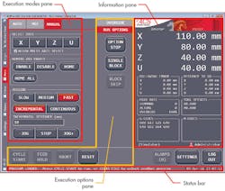
3. CNC-style HMIs provide customization tools, including the ability to add graphical buttons, tabs, and operation screens to optimize the laser-micromachining process. (Courtesy of ACS Motion Control)
CNC-style HMI
CNC-style HMI systems execute machine code programs to perform their manufacturing process (Fig. 3). These machines are typically found next to other CNC machines, including lathes, mills, and routers. The CNC-style HMI is customizable, and the development platform provides standard features right out of the box.
The CNC HMI loads, edits, and executes numerical-control (NC) files with standard RS-274 and user-defined G-codes. G-codes are created by a computer-aided-manufacturing (CAM) software post-processor. Flexible programming offers flow control options to stop, hold, single-block run, block skip, and feed-rate hold the process on the HMI. The operator can real-time monitor directly on the HMI and observe the program execution, the axis position, feed rates, g-code, and any faults. The HMI will also offer multiple logins for different users, technicians, and administrators.
One key advantage of this type of system is that it’s customizable, which allows the developer to design application-specific HMI options with ease. These could be anything from custom tabs and buttons to additional operation screens. High-level sophisticated customizations involve process visualization and/or integration of other equipment, such as safety sensors, laser displacement sensors, and machine cameras.
Integrated Graphical HMI
When the system operator is not a traditional CNC machinist, the more-preferred option is an integrated graphical HMI (IG-HMI). IG-HMI systems are typically used in applications such as flexible PCB drilling and cutting, polymer display processing, semiconductor processing, high-precision additive manufacturing, and precision optics manufacturing.
An IG-HMI imports the laser path directly from the CAD file. The machine code is automatically generated and executed on the motion controller. Out of the box, the IG-HMI has several built-in functions such as laser marking, etching, cutting, drilling, and additive manufacturing. The majority of CAD file formats are supported, including DXF, DWF, and STL. The IG-HMI allows of manipulation of these files directly in the interface. The motion axes parameters are configurable and monitored in a single window.
The IG-HMI natively supports galvanometer scanners and machine cameras; real-time monitoring and data collection are also standard features. Prior to performing the laser micromachining, the IG-HMI can offer a simulation view to ensure the process is as desired.
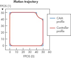
4. With the implementation of HMI software, the operator can optimize the laser machine path by adding in corner profiles that were not included in the original CAM profile. (Courtesy of Industrial-lasers.com)
The CNC-style HMI and integrated graphical HMI both offer performance optimization for motion performance. Profile generation or the commanded motion path and servo performance affect motion performance. The accuracy of the actuators and stages following the command motion path are crucial. Modern controllers allow users to optimize the energy profile, motion segment blending, and corner smoothing to enhance performance (Fig. 4).
Adaptive servo control algorithms, auto tuning, and advanced pulse-width-modulation drive technologies enhance the CAM profile to a more desired controller profile. This allows the operator to apply their expertise and obtain a more desired result.
Besides motion performance, modern HMI systems provide flexibility with respect to position-based output synchronization. With the motion-control network, the software of the module configures the synchronized outputs based on the motion of any combination of axes. The laser-control module operates the various laser-control modes, making it easier to be applied across a several different applications.


