Download this article in PDF format.
A linear actuator combines linear-motion components and a linear shaft motor (direct drive) in one assembly. Such an actuator creates motion in a straight line, in contrast to the circular motion of a conventional electric motor. These devices are used in machine tools, industrial machinery, computer peripherals (e.g. disk drives and printers), valves, and dampers, and in many other applications that require linear motion.
When designing with standard linear systems, a linear actuator can reduce overall machine design costs, eliminate the effort associated with integrating lower-level components and assemblies, and contain application-tested and optimized construction. Using linear-shaft-motor direct-drive technology eliminates the need for an additional belt or screw, gearhead, or motor as in many electromechanical positioners. In turn, high-speed acceleration, high accuracy, and repeatability all become possible.
A linear actuator with linear shaft motors has some essential advantages in typical applications. These include no-wear components, no seals to fail, and, thanks to those two benefits, enhanced reliability and mean-time-between-failure (MTBF) factor.
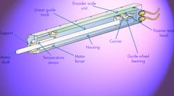
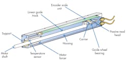
1. This linear actuator highlights the components necessary to control temperature variation, such as a passive read head and temperature sensor.
Often, linear actuators are used in motion applications with linear position feedback, much like encoders in industrial controllers. In numerous cases, encoders function as measuring devices to measure the linear position or linear-dependent data of production equipment or the linear motion of components.
In many applications, linear actuators require very accurate positioning (about 2-4 µm), especially in X, X-Y or X-Y-Z stages. For linear actuators—which are fixed to the machine element—to work properly without positioning errors, they need feedback elements like the internal and external condition ambient temperature (Fig. 1).
Temperature Expansion
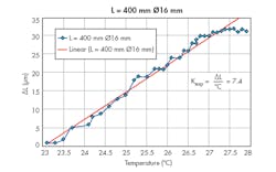
2. For a shaft length of 400 mm and a shaft diameter of 16 mm, the coefficient of thermal expansion is equal to 7.4 μm/°C.
Temperature may impact the extension or shortening of an actuator’s working elements, in particular the axial moving shaft length. Consequently, this will significantly decrease accuracy (up to 40 µm, depending on physical properties of the shaft and other elements of the actuator) and repeatability because the driven element is fixed directly to end of shaft.
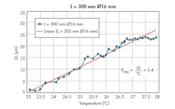
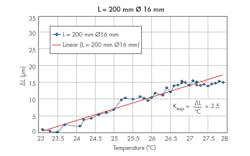
In Figures 2-4, thermal expansion is measured as a function of temperature change for an actuator shaft formed of identical material, but having different geometries. It’s seen that the coefficients of thermal expansion are different in these three cases.
Thus, in Fig. 2, for a shaft length of 400 mm and a shaft diameter of 16 mm, the coefficient of thermal expansion (Kexp) given by ΔL/°C is equal to 7.4 μm/°C. In Fig. 3, for a shaft length of 300 mm and a shaft diameter of 16 mm, Kexp is equal to 5.4 μm/°C. In Fig. 4, for a shaft length of 200 mm and a shaft diameter of 10 mm, Kexp is equal to 3.5 μm/°C. This means that even for a low-gauge shaft having a diameter of 10 mm and a length of 200 mm, a rise in temperature of only 1°C will give rise to a thermal expansion of 3.5 μm. In semiconductor fabrication and other nanotechnology applications, such a deviation is critical.
3. For a shaft length of 300 mm and a shaft diameter of 16 mm, the coefficient of thermal expansion is equal to 5.4 μm/°C.
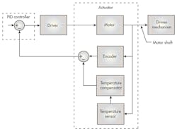
In Figure 5, the control unit block diagram shows the functionality of the linear actuator for achieving the required temperature compensation. This is so that the motor shaft can be moved forward or backward by a precisely controlled distance regardless of local changes in the shaft’s temperature.
As already described, the actuator is comprised of a motor forcer that advances a motor shaft forward or backward and is coupled to a driven mechanism that’s external to the actuator. In Fig. 5, motor shaft is shown schematically with the arrow that couples the shaft of the motor to the driven mechanism. Also shown is the encoder—it’s responsively coupled to the shaft of the motor, and determines its position.
The output of the encoder is fed to an input of a first subtract operation. The output has a negative value that’s coupled with the output of a temperature compensator. Thus, the first subtract generates a signal corresponding to the difference between the nominal position signal of the shaft and a temperature-compensation signal.
The temperature compensator is responsive to the instantaneous temperature of the shaft, as measured by the temperature sensor for determining a compensation signal. When fed to the first subtract, it produces a corrected encoder difference signal, which takes into account the fact that the shaft has expanded or contracted from a nominal baseline length. The nominal baseline length is established at a known baseline temperature according to whether the instantaneous temperature of the shaft is higher or lower than the baseline temperature (Figs. 2-4, again).
4. For a shaft length of 200 mm and a shaft diameter of 10 mm, the coefficient of thermal expansion is equal to 3.5 μm/°C.
The corrected encoder difference signal is fed to a proportional-integral-derivative controller (PID). The PID continuously calculates an error value as the difference between a desired driver signal and the corrected encoder difference signal. It minimizes the error over time by adjusting a control variable u(t), corresponding to the position of the motor shaft to a new value determined by a weighted sum:
where Kp, Ki, and Kd are all non-negative and denote the coefficients for the proportional, integral, and derivative terms, respectively. In this model:
- P accounts for present values of the error. For example, if the error is large and positive, the control output will also be large and positive.
- I accounts for past values of the error. For example, if the current output is not sufficiently strong, error will accumulate over time, and the controller will respond by applying a stronger action.
- D accounts for possible future values of the error, based on its current rate of change.
5. Above is a control unit block diagram showing functionality of the linear actuator, which is used to achieve the required temperature compensation.
The temperature compensator includes a lookup table or ROM, which stores measured values of the thermal expansion or contraction parameters depending on the geometry dimensions of shaft. The table provides linear compensation values that are used for different temperatures, relative to a known measured baseline. These values take into account the shaft’s geometry as well as the material from which it is formed, and are used in real time to establish a negative or positive offset that must be added to the movement of the shaft.
Take Your Position
The offset is necessary so that when moved to a desired position, it reaches exactly the desired positon and not to a position that is incorrect by the instantaneous expansion or contraction of the shaft. The latter is due to departures of the shaft’s actual temperature from the baseline temperature. If desired, the temperature compensator may also include an interpolator for in-between values when the lookup table does not store the offset for the shaft’s measured instantaneous temperature.
The positioning drive-mechanism, which serves to position the executive mechanism carried by the shaft, is controlled by a control unit. It considers the temperature-change dimensions of the shaft resulting from the temperature changes from the sensor, which is placed directly on the shaft. This achieves a machining precision that is independent of temperature, temperature changes from the machine overall, and temperature changes in the single parts of actuator and the shaft.
To move a shaft of linear actuator by a specified distance, use a linear encoder with a passive (wireless) read head, which includes a scale unit arranged into a hollow body of the actuator and extends in a direction of measurement. The passive read head is fixed to a carrier that connects to the shaft of the actuator. Because the read head is passive, it has no bending wires and no need of a carrier for them. This significantly increases reliability and simplifies the actuator’s design.
To increase the efficiency and precision of a linear actuator based on linear shaft motor, decrease the quantity of friction pairs and prevent, as much as possible, temperature changes of linear (elongation or shortening) dimensions of transmission-system mechanical parts. This allows for a design that optimizes linear transmission systems.
Conclusion
For ultra-high-precision applications (2-4 µm), a linear actuator that uses linear shaft motors can help deliver a simpler design, higher precision, and repeatability of positioning. To achieve the aforementioned parameters, it is necessary that the heating temperature data be transmitted directly to the control unit block. The rise in temperature can be caused by different physical factors, such as a change of ambient temperature, friction, heating forcer, and currents from the shaft motor (i.e., eddy currents also called Foucault currents).
While it does slightly increase the amount of work and cost of the linear motor, the ability to transmit temperature data into the control unit prevents the thermal changes from influencing positioning and repeatability of linear actuator’s end shaft position. Controlling the transference of the actuator shaft, taking into account the temperature values of the shaft, helps increase the machining precision and repeatability of the mechanism.
