For True Linear Position, Embrace Magnetostriction
You just finished the design of what is basically a fancy linear stage. Does your motor controller know exactly where the carriage is? Like, really where the carriage is?
Newsflash, buddy: It does not. Sure, you have an encoder on your motor, but that isn’t measuring the actual position of anything but the motor shaft. Can you live with an inferred position rather than a measured one? Can your system live with it?
You can’t trust an encoder to tell you where the moving bits really are, because it doesn’t actually know. Oh, you have limit switches? Those are mounted at each end of the stage, right? How are those switches to know what’s goes on in the space between them? Again, they can’t know.
Calculating position is like sending a delivery truck out for multiple deliveries. They left and came back. They were gone for what seemed like the right amount of time, but you have no way of knowing if they stopped everywhere they were supposed to go. By the time you do find out that they missed a delivery, it may be too late.
What’s going on, you ask? I’ll tell you what’s going on. This article is like a reverse Blow Pop: soft outer shell, hard-as-dang-rock inner core. And guess what, pal? You just got past the chewy outside. But don’t worry; you’re going to enjoy this next part, ’cause it’s going to teach you how to solve this problem with a type of sensor that you probably didn’t even know existed.
Any closed loop mechanical system uses sensors to report changes in position to a controller. These sensors usually report the angular position of a shaft and are typically installed on a motor—or, mechanically speaking, very close to it. Aside from motor control, the sensor data is also used to extrapolate the position of moving elements in the system. The limitation of this method is that the true position of the moving part is not known, but inferred.
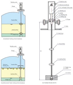
1. Inside tanks of gasoline, like underground at a gas station, the liquid level needs to be detected. The typical solution is a magnetostrictive probe sensor. (Courtesy of magnetostrictivelevelsensors.blogspot.com)
Stumbling Blocks
Many factors aggravate the discrepancy between extrapolated position and true position. Stiction and the elasticity of driven elements will influence the error. Inaccuracies in components like screws and belts are also contributors. Longer setups will amplify deviations as well as other unwanted effects, like vibration. If a design cannot handle the inaccuracy of an inferred position, additional sensors must be applied.
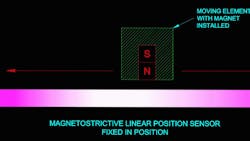
An often-overlooked solution involves magnetostrictive linear-position sensors (Fig. 1). A surprising number of engineers I have interacted with did not know these were available. Strange, considering the technology is very mature. The principles that make these devices possible weren’t discovered last week. These people just aren’t aware that the same phenomenon that makes transformers hum can be harnessed and used as a sensor. If they have heard of it, it seems to be thought of as a technology solely for liquid level detection.
Magnetostrictive linear-position sensors measure the absolute position of a magnet, wherever it is, along the length of the sensors body (Fig. 2). The magnet is stuck onto the thing you want to keep track of.
2. Magnetostrictive linear-position sensors measure the absolute position of a magnet that lies anywhere along its length.
How They Work
The cornerstone of these sensors is a wire waveguide made from specially selected magnetostrictive materials. This wire is illustrated in Figs. 3 and 4. Magnetostrictive materials change their shape during the process of magnetization.
To start the measurement process, a microcontroller in the control unit supplies a very brief electrical pulse to the wire while simultaneously starting a high-speed timer (Fig. 3). The pulse from the MCU energizes the waveguide and causes it to react to the magnet. This reaction manifests itself in a way very similar to a struck guitar string. A soundwave is created. This wave races away from the point where the magnet interacted with the momentarily energized waveguide (Fig. 4). In fact, if you place your ear right next to one of these sensors, you can usually hear the wire as it is magnetically plucked.
3. Shown is a simplified representation of the working inside a magnetostrictive position sensor.
The MCU runs the counter until the pickup coil senses the sound wave. The final counter number, along with the the speed of sound in the waveguide material, is used to calculate the distance of the magnet from the control unit.
4. The energized waveguide reacts with the magnet and plucks the waveguide. This causes a sound wave to race away from the point where the magnets field interacts with the wire.
Sensor Benefits
These sensors lend themselves to harsh and filthy conditions. The sensors themselves are typically sealed against dust, grime, and fluids with IP67 ingress ratings or better. If the situation demands it, intrinsically safe models with ATEX ratings are also available.
Proper operation has only three requirements: the sensor body must be installed parallel to the axis of movement, the magnet must be affixed to the moving element of the system, and the magnet must stay within the detectable range of the sensor at all times. Truth be told, they can often tolerate some minor misalignment of the magnet.
Some of the applications that can benefit from such robust sensors are machine tools with coolant flooding everywhere, manufacturing equipment, and niche applications in robotics. They can also be used for test and calibration. For example, a magnetostrictive position sensor can be used to map the inaccuracies of lead screws.
Magnetostrictive linear-position sensors boast a lot of attractive features, but the clincher—the coup de grâce of these devices—is their accuracy, precision, and resolution. Resolutions of 1/10,000 of an inch are not unheard of, and they don’t have to be zeroed after they have been powered down. They are reporting true position the moment they are turned on. Many of these sensors also feature temperature compensation. This allows them to maintain accuracy despite varying ambient conditions. Put another way, the ruler won't shrink or swell when it gets hot or cold.
About the Author
Cabe Atwell
Engineer, Machinist, Maker, Writer. A graduate Electrical Engineer actively plying his expertise in the industry and at his company, Gunhead. When not designing/building, he creates a steady torrent of projects and content in the media world. Many of his projects and articles are online at element14 & SolidSmack, industry-focused work at EETimes & EDN, and offbeat articles at Make Magazine. Currently, you can find him hosting webinars and contributing to Penton’s Electronic Design and Machine Design.


