Download this article in PDF format.
There is a whole lot to know about servo motors and drivers. You could make a career out of specializing on that one topic. This article is a very small collection of some of the features to consider regarding tuning servo-motor systems. In no way would this be considered a comprehensive list, and it isn’t meant to be. It’s just enough information to keep you pointed in the right direction.
I have witnessed professional engineers spend absurd sums of company money on equipment with features way more than what the situation demanded. They didn’t really understand what they were looking at, so they went with the biggest and most full-featured devices that they could get. While it is nice to get the equipment with extra power and options, it’s also really expensive. I have also witnessed this phenomenon in reverse where some poor, underfeatured piece of equipment was press-ganged into a role it could barely fulfill.
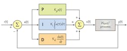
This article refers to PID-controlled motors paired with a feedback device, like an optical encoder. We’re not talking about the little gearbox motors used in hobby applications that employ a potentiometer for feedback. Those operate on different principles.
Dollars and Sense
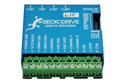
At the low end of the price range, most servo drivers use trim-pots to tune the control algorithm. A good example of this is the G320X servo drive from Geckodrive Motor Controls. While drivers like these can be fantastic performers, adjustments to the tiny board-mounted potentiometers are vague. This can become an issue because trim-pot settings are hard to replicate. When working on multiple systems, it will be impossible to set all potentiometers in the same manner by eye.
Analog adjustments also have to be performed manually by a human operator. Automating the tuning process of these types of drives is difficult, if not impossible.
In a production environment, it will be time-consuming to teach workers how to accurately calibrate a drive that uses trim-pots. Even engineers new to the process have a hard time with it.
Going Digital
A pricier feature, but one that may be worth the expense, is digital tuning. Digital tuning allows an operator to manipulate the PID variables of the control algorithm via connection to a computer or on the drive itself. This feature really shines when working on multiple servo systems or trying to reduce takt time in production.
Because the variables are digital, they are definitive and can be recorded. That data can be used to adjust all subsequent drives, provided they are installed in similar systems. Minuscule differences between identical setups will result in the need to slightly tweak the variables. Though now, the final adjustments can be done from a point very close to ideal.
That variable data can also be used for troubleshooting. Large changes to the initial PID variables during assembly can indicate assembly error or a problem with a component. Over the life of an installed system, regular adjustments can be recorded and analyzed to spot trends.
Self-Tuned
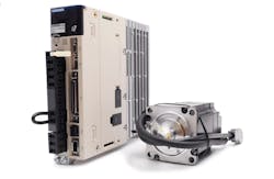
An even higher-cost option involves drivers that tune themselves. However, the efficacy of these types of drives is typically commensurate with their cost. The per unit costs are often several thousands of dollars. As impressive as self-tuning drives are, all but the best typically need human intervention to make final adjustments.
Servo motors can be tuned by themselves on a workbench to get started, but they will ultimately have to be adjusted when installed into their final position. The PID loop’s variables control the motor and whatever the motor is attached to, as a whole. Changing any part of the whole will, in turn, require changing the PID variables.
Practice Makes Perfect
As a final note. Hands-on experience is needed to really wrap your mind around these different adjustment methods. It is best to practice on expendable equipment. That way nothing expensive or important will be destroyed during the learning process. Smaller equipment is also less likely to cause personal injury.
A prebuilt linear stage that can be paired with various driver and motor combinations is ideal for this task. Adjusting trim-pots with your hands will give you a feel for each of the PID variables. That experience will be invaluable when making decisions about selecting servo motors and drivers.


