Making the Right Shaft Connections
Download this article in .PDF format
Before installing industrial belt drive components, you need to start with a basic understanding of the various types of mounting devices used to attach pulleys to shafts. Knowing the advantages of these different devices, and how they operate, helps prevent installation errors that cause drive component damage and costly equipment downtime.
Several types of tapered bushings can be used to mount V-belt sheaves and synchronous belt sprockets, hereafter called pulleys, to drive shafts. These bushing types include keyed versions, for locking to the shaft, which are described in this article. Other types do not require keys (see box) and will be covered in a future article.
Keyed tapered bushings
A common device for attaching pulleys to motors, gearboxes, and shafts is a keyed tapered bushing, which is typically made of gray iron, steel, ductile iron, or sintered steel.
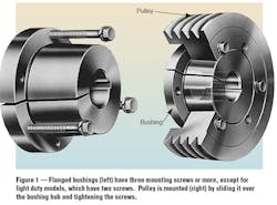
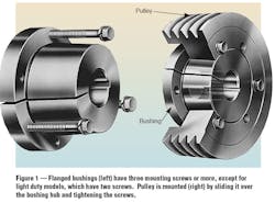
With these bushings, a tapered bore in the pulley fits over a mating tapered outside diameter on the bushing, Figure 1. To attach a pulley, a mechanic tightens mounting screws, which draw the tapered surfaces of the bushing and pulley hub together. Forcing the mating tapers together creates a wedging action between the bushing and pulley, and between the bushing and drive shaft. The bushing has a radial slot or saw cut, that lets it tightly grip the shaft under the wedging action. The gripping force between bushing and shaft is comparable to that of a press fit so that the bushing transmits torque and resists slippage. Correctly applied, the bushing eliminates pulley wobble as well as fretting corrosion on the shaft.
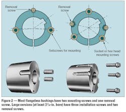
To remove a pulley, the mechanic tightens one or more removal, or “jackapart,” screws, which separates the pulley and bushing without damaging the shaft or drive components.
For a given bushing OD, manufacturers offer several different bore sizes to accommodate different shaft diameters. For example, flanged bushings with a 2-in OD are available with bore sizes ranging from ½ to 13/16 in. One bushing can also be used for pulleys of different widths, and pulleys grooved for different belt cross sections.
Some manufacturers offer bushings with unfinished small-diameter bores and without saw-cuts. This lets the end user rebore, then cut on-site, achieving quick turn-around when unusual bore and key sizes are needed.
Flanged bushings, Figure 1, are used in a wide range of heavy-duty V-belt and synchronous belt drive applications. Designed according to Mechanical Power Transmission Association (MPTA) QD1 Detachable Bushing and Mating Hub Guidelines, these bushings are well suited for high power drives subject to large pulsating or vibrating loads. Standard bore sizes range from ½ to 7-in. or more.
Flangeless, or flush-mounted, bushings, Figure 2, are commonly used on chain drives and most European belt drives. Those made from special materials, such as stainless steel, are well suited to the food industry because of their smooth, easy-to-clean surface. Again, bore sizes range from ½ to 7-in.
Shaft keys
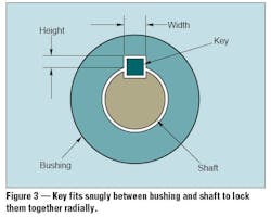
During assembly, a key is inserted into machined keyways in the bushing and shaft to lock them together and prevent the shaft from rotating in the bushing, Figure 3. These keys are generally made from bar stock and come in square, rectangular, and tapered shapes. The Woodruff key, used primarily in machine and automotive applications, is shaped like a half-moon.
An improperly fitted key — either too tight or too loose — can cause key or hub failure. Therefore, to ensure a snug fit, width and height dimensions of both key and keyways must be held to tolerances specified by ANSI standard B17.1 for Keys and Keyseats.
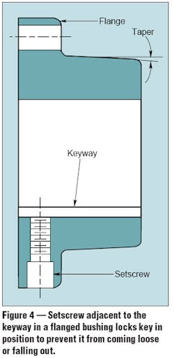
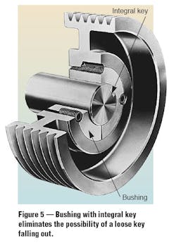
In most flanged bushings, a setscrew in the flange, Figure 4, tightens against the key to prevent it from working out of the keyway. This feature is especially useful for applications subject to vibrating or pulsating loads and in vertical shaft applications. One type of bushing has an integral key that is formed as part of the bore, Figure 5, so there is no separate key to come loose. Both types of bushing are popular in vertical shaft installations.
Selection
Some industries traditionally use certain bushing types regardless of their features. But in most cases, you should know the benefits each type offers when selecting one for a specific pulley mounting application.
Advantages of flanged bushings include:
• Long bore length minimizes axial runout (non-perpendicularity to shaft).
• Symmetrical hole pattern and saw slot opposite the setscrew provides good balance.
• Setscrew keeps key in place, which is good for vertical shafts and for high horsepower drives with large pulsating or vibrating loads.
Disadvantages of flanged bushings are:
• Flange increases weight and requires more space for mounting.
• Some pulley sizes and shapes can only be mounted one way — either conventional or reverse.
Advantages of flangeless bushings include:
• Larger taper angle permits tightening the pulley with less displacement along the shaft. This makes it easier to accurately locate the pulley on the shaft where precise positioning is required.
• Safer operation due to lack of protruding screw heads.
• Full length of the bushing supports the pulley.
Disadvantages of flangeless bushings are:
• Can’t be installed as quickly (in small sizes).
• There is no setscrew to lock the key in place.
Installation and removal tips
When a pulley fails to stay tight and true on the shaft, improper installation may be the cause. When installing a pulley, first clean oil, paint, and dirt from all tapered and mating surfaces of the pulley, bushing, and shaft.
Don’t lubricate these components. Lubricating the mating tapered surfaces reduces friction. With lubricated surfaces and the same screw torque, the tapered surface mechanical advantage is greatly increased compared to dry surfaces. This causes excessive radial pressure, resulting in cracking of bushing or pulley hub.
Adhere to the manufacturer’s recommended torque values for tightening installation screws. Tighten the screws in an alternating pattern, repeating the pattern several times to obtain the desired wrench torque.
When installing bushings (especially the flangeless type) avoid using a worn wrench, which can strip the screw head and cause a loose assembly. For increased gripping force, tap the face of the bushing with a drift pin or sleeve, then retighten the screws to the recommended torque setting. Do not strike the bushing directly with the hammer.
Excessive screw torque can damage bushings or pulleys. Also, uneven pressure on jack-apart screws may ruin the bushing, making removal difficult without damaging the pulley.
Be sure to use bushings with shafts of the correct size and tolerance. Shaft tolerances are specified in the ANSI B4.1 Standard for Limits and Fits. For bushing tolerances, see the MPTA Detachable Bushing and Mating Hub Guidelines. A flanged bushing should have a 1/8 to 3/8-in. gap between its flange and the pulley hub. The absence of this gap indicates either an undersize shaft or oversize bushing bore. In either case, the bushing flange can bottom against the pulley, so that it doesn’t develop enough force to grip the shaft tightly.
Pulleys mounted with tapered bushings rarely loose their tight fit, but overload or improper installation can cause them to loosen. During inspection or maintenance, check for these conditions that cause looseness:
• Cracked pulley hub.
• Other damage to pulley, shaft, bushing, or mounting screws.
• Improper mating of tapers.
• Missing keys, particularly on vertical shafts, and on horizontal shafts subject to vibration.
• Lubricant that leaks from components such as chain, gear, or grid couplings.
• Bushing bored to the wrong diameter.
Keyless bushings
Besides keyed bushings, there are several types of keyless locking devices that also use the tapered wedge principle. These keyless bushings convert clamping action between inner and outer tapered rings into radial pressure that locks the device to the shaft and pulley.
The main advantage of keyless bushings is their ability to transmit high torques. However, they are available in a limited number of bore sizes and tend to cost more than keyed types.
Many of these keyless bushings are found in industrial applications where high axial forces or shocks occur. Some types can be used over damaged shaft keyways, but must be carefully locked and centered. Others require a smooth shaft without a keyway.
Keyless bushings apply locking pressure uniformly around the shaft circumference, thereby enabling the use of hollow shafts for weight reduction, as long as the shafts have adequate strength.
These bushings also let you use solid shafts that are smaller in diameter but equal in strength to keyed shafts. The ease of positioning these bushings in axial and angular directions makes installation and removal a fast and simple operation.
Daniel Schwartz and Gary Porter are product application engineers, The Gates Rubber Co., Denver.
