This file type includes high resolution graphics and schematics when applicable.
When designing a control system, where the safety system is to be networked, where would you start? To understand the basis for safe motion control, the first place to look would be the PLCopen safety standard. This would give you a vendor-neutral look at the functionality available to programmers and how to implement it in the control architecture. Most controls engineers are comfortable using the PLCopen standard for the motion functions in a system and may have even written their own functions.
However, safe motion control can be difficult to understand straight from the standard. Here we will look at what is explicitly stated in the standard and what it means to controls engineers attempting to apply these functions to their systems.
Safe Motion Control (SafeMC)
SafeMC is the combination of safety-rated software and hardware to ensure safe operation, at the same time expanding the capabilities of a motion system —e.g., avoiding unnecessary and costly stop and restart procedures that can involve re-homing and resynchronizing linked axes. This is achieved through constant self-monitoring to keep within defined operating parameters as defined by a risk assessment. The risk assessment is necessary to identify the hazards of a machine and to determine the safety measures that should be implemented to protect operators and maintenance personnel.
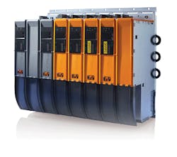
The hardware is made up of functionally safe-rated encoders mounted to servo motors and safety- rated servo drives. The safe encoders are specially mounted to the motor to prevent misalignment and slippage that would affect the accuracy of the position feedback. The feedback is sent redundantly to the drive with checksum to prevent corrupted data and ensure its accuracy. The safe servo drives have permanent redundant feedback cards to ensure that the drive evaluates that position correctly. On the software side, the PLCopen Safety standard is the backbone of safety-rated functionality. It ensures that the software functions, once the full safe application has been verified, fall within applicable machine safety standards and serves as a measuring stick for the safety of a machine during a risk assessment.
Available Functions
The main safe motion control functions defined by the PLCopen Safety specification pertain to Emergency Stop, Safe Stop 1, Safe Stop 2, and Safely Limited Speed. PLCopen Safety also defines many other Safe Functions available that can be used to control and monitor safe hardware (light curtains, two-handed controls, machine guarding interlocks, etc.) in conjunction with the safe motion control focused functionality. Also, most automation suppliers have implemented their own safe functions to extend these capabilities while complying with this standard.
To better define the Emergency Stop, Safe Stop 1, Safe Stop 2, and Safety Limit Speed functions from the PLCopen safety standard, each has been summarized in the following sections.
Emergency Stop (E-Stop)
According to the PLCopen Safety standard, “The function block is a safety-related function block for monitoring an emergency stop button.”
This function block (FB) does not replace an emergency stop button. It does allow an emergency stop button to be wired into safety rated machine, I/O and that E-Stop information can be passed back to the control system along the machines I/O bus. This can minimize wiring and have the additional benefit of allowing a machine builder to distribute multiple E-Stop buttons around a machine to normal operation locations without the need to run all the wires back to the electrical cabinet. It also means that the control system can monitor the channels on the E-Stop for activation.
In addition, it can monitor/diagnose the physical E-Stop circuit and minimize (or even eliminate) the need to periodically check the E-Stop circuit, plus all of the wires running back to an electrical cabinet, for faults like broken wires or stuck contacts. This function is a fundamental part of a safe motion system, as the activation signal from this FB is frequently used to activate Safe Stop functions. These, in turn, bring the motion system to a stop depending on the application specific Stop Category.
On a modular machine line, E-Stops can be prewired onto subsystems into machine-mounted I/O modules, and the only wiring that needs to be connected to another subsystem would be the fieldbus communication cable. This allows an expandable safety system to be simply implemented. Also, during the commissioning and validation process for the safety system, the machine’s controller can be used to check if any wiring faults are present in the system through diagnostic tools instead of the manual process of checking wiring connections from where the E-Stop is placed and the associated electrical cabinet where the connections would be traditionally landed.
Safe Stop 1 (SS1)
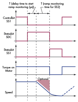
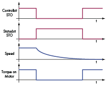
According to IEC 61800-5-2:2005, “SS1 initiates and monitors (or controls)...deceleration...within set limits to stop the motor and initiates the STO [Safe Torque Off] function when the motor has stopped; or initiates the motor deceleration and initiates the STO function after an application specific time delay. The STO function as defined by the same standard: Power, that can cause movement …is not applied to the motor or has been removed.”
The purpose of this function is to cause the motion system to stop according to a Stop Category 1, as defined in the standard EN60204. This FB allows a user to initiate a user defined controlled stop (speed-controlled, torque controlled, etc.) to quickly decelerate a single-motion axis before removing power to the motor. The FBs safety function is twofold: First, it monitors the speed of the axis. When it reaches standstill, it sets an output for use in the application code and initiates an STO function on the drive. Secondly, it has a timer that is monitored alongside the axis velocity; if the axis is not at standstill within an application-specific time period, it assumes the drive is unable to complete its request for a controlled stop. The safety system then tells the drive to initiate an STO function to ensure the motor is not powered and will come to a stop.
Note: The FB does not execute the stop function. The stop function is the responsibility of the drive system.
A good example application for the SS1 function would be for any roll-to-roll process, such as a rewind stand. The web (paper, metal, rubber, textile, etc.) has an operational or safety issue (like a partial tear, complete web break, etc.), and the operator activates the E-Stop command. In a traditional system the power to the motor is removed via an STO circuit on the drive and the spool would spin out under its own inertia or require a large mechanical brake to slow down the load.
With the SS1 function in place, the operator would command a stop via the E-Stop. Then, using the controller and a piece of software, a stop command would be sent to the drive with a high deceleration. The SS1 function would monitor its timer and, after the defined period, it would initiate the STO circuit on the drive. This would considerably shorten the time required for the spool to come to a stop, and would greatly decrease the wear on an external mechanical brake—if it did not remove the need for said brake entirely.
Safe Stop 2 (SS2)
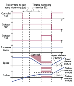
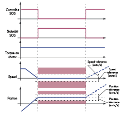
According to IEC 61800-5-2: 2005, “Safe Stop 2 (SS2)...initiates and monitors…deceleration …within set limits to stop the motor and initiates the Safe Operating Stop (SOS) function when the motor has stopped; or initiates the motor deceleration and initiates the SOS function after an application specific time delay. The SOS function as defined by the same standard: Ensures that the motor remains stopped by resisting external forces.”
The purpose of this function is to cause the motion system to stop according to a Stop Category 2, as defined in EN60204. This is defined as a controlled stop with power left available to the machine. The function of SS2 is that when a stop is commanded, there is a time-monitored stop condition similar to SS1 that commands an SOS function. The SOS, unlike the STO, maintains power to the motor and monitors, within a set application specific position tolerance, both the position and the velocity of the axis.
The axis is monitored until the function is disabled or the motor moves outside of the tolerance. If the axis is moved outside of the position tolerance while the function is active, the safety system will cause the STO function to be called as a failsafe response. In short, the SS2 allows a machine to safely carry on where it left off before the stop occurred.
SS2 with SOS can be highly useful for any process that requires synchronized motion. Since it is not limited to a single axis, this can be integrated with as many axes as are a part of the coordinated movements. The fact that the axes can remain powered means that they never lose synchronization, and can be started right away after the issue for the stop has been cleared.
In an application like printing, labeling, or perforating, this can save an end user a lot of time spent bringing the various axes back to a known start position before synchronized motion can be started again. Another significant benefit for end-users in similar applications is that there is no wasted product during the restarting process. These gains can lead to significant savings for OEMs to pass on to their end-user customers.
Safely Limited Speed (SLS)
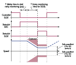
According to IEC 61800-5-2: 2005, “The Safely Limited Speed (SLS) function prevents the motor from exceeding the specified speed limit.”
The purpose of this function is to activate the monitoring of the velocity of an axis and compare it against a defined application specific speed limit. The application-specific speed limit is determined during the risk assessment, and more than one speed limit can be determined depending on the machines operation modes. If the defined speed limit is violated, then the system must come to a stop by either of the previously mentioned stop functions (SS1 or SS2). This function can be enabled and disabled according to many different application situations with different speed limits for each.
The biggest benefit is the ability to keep an axis up and running safely while other operations are performed in and around the axis. In practice this can decrease the time spent stopping and starting a machine to perform simple setup, changeover, or maintenance tasks. When used properly and integrated into a machine line, this function can have a large impact on up-time and operational efficiency.
If this function is applied along a modular machine line, then a designer can use this function to keep a machine line operational while a jam/operational issue or setup process is being handled in the middle of the line. Limiting the speed of multiple axes up and downstream from the affected machine component means that other sections of the line can still perform their tasks with a much lower chance of being starved or having an overflow.
References:


