Electropneumatic Valves: A Better Option for Motion Control
This file type includes high resolution graphics and schematics when applicable.
Today’s manufacturers routinely demand exacting precision and split-second timing from their high-speed production systems. And that has automation engineers constantly on the lookout for cost-effective ways to improve positioning control and accuracy.
Electromechanical positioning has typically been the most common method of motion control in automation systems. But an alternative that’s gaining ground is electropneumatic positioning. Systems based on this technology rely on precision valves to control flow or pressure and, in turn, move an actuator to a required location. Here’s a closer look.
Electromechanical Basics
In electromechanical systems, linear devices such as profiled rails, ball screws, and linear modules driven by electric motors lift, move, and place components. These systems can provide excellent positioning accuracy. Accurate positioning refers not only to an actuator’s endpoint accuracy, but also to the accuracy of its position at any selected point along a path of motion. In high-speed automation, precision motion sequences—not just in terms of positioning, but also in its timing—are crucial to manufacturing speed, throughput, and quality.
Electromechanical positioning can meet these requirements. However, electromechanical devices also have some inherent drawbacks that, over the long term, can increase manufacturing costs, cause production problems, and hurt overall productivity.
Engineers are learning that in many cases, pneumatic positioning holds numerous advantages, including greater productivity, better repairability, and lower total cost of ownership. Like electromechanical devices, pneumatic actuation systems can accurately control positioning throughout a motion sequence—not just at the endpoint. And they provide engineers with a number of implementation options, letting them select the best design for a given task.
Pneumatic Advantages
For example, electromechanical positioning systems can heat up and undergo temperature-related performance changes, as well as accelerate wear and tear. That, in turn, requires significant downtime to cool. In fact, lower-cost systems often are only capable of 50% duty cycles, spending as much time off as they spend working. Pneumatic positioning systems, on the other hand, do not have mechanical parts that can overheat. This permits a 100% duty cycle with components that stay cool and can work around the clock.
Also, pneumatic positioning systems are often also more energy-efficient. For instance, electromechanical systems consume electricity simply to hold a position. And without power, electromechanical systems reset themselves, losing any previous work leading up to a power outage. Productivity suffers as a result.
Pneumatics doesn’t have this problem. When designs use pneumatic flow control, a valve in the center position blocks airflow in either direction and the cylinder piston automatically stays put. In the event of power loss to a production system or plant, it is much easier to restart production with pneumatic positioning systems. Proportional pressure control and normally closed valves provide the same benefits when power is lost.
In addition, pneumatic components are relatively easy and economical to repair. When pneumatic cylinders break or wear out, they can be repaired or replaced inexpensively. On the other hand, when an electromechanical system has issues, it typically requires a costly new electric drive.
These advantages, combined with the inherent low-maintenance nature of pneumatic devices, create a significantly lower true cost of ownership as compared to that of an electromechanical setup. In fact, the cabling alone on an electromechanical device can cost more than an entire pneumatic system.
Flow Control
Pneumatic-powered actuation provides a proven method for accurate and reliable positioning. Most pneumatic positioning systems combine control valves, cylinders, and simple sensors; and rely on directional flow control to control positioning. Such a system monitors piston position feedback and decides in which direction air needs to flow to achieve the desired position. Shifting a valve and letting compressed air flow into the proper cylinder port extends the actuator to the required position. Reversing the valve retracts the cylinder in the opposite direction.
This type of system provides a broad range of directional flow control, translating to precise, incremental positioning control. The valves for such a system are selected based on the bore and stroke of the pneumatic actuator. Air flow can generally be controlled in the range of 0 to 1,000 liter/min.
Still, there are some drawbacks to using pneumatic flow control for positioning. The most common concern is associated with a basic limitation of pneumatics: Such systems cannot be perfectly sealed, and an incremental or intermittent loss of air and pressure is unavoidable.
With directional flow control, minor leaks cause the pneumatic cylinder piston to move slightly. The positioning system’s controller receives motion feedback from the sensor, and the controller responds by slightly adjusting flow to compensate for piston movement. This slight but constant back-and-forth motion, known as dithering, negatively affects system accuracy and functionality.
This file type includes high resolution graphics and schematics when applicable.
Proportional Pressure Control
This file type includes high resolution graphics and schematics when applicable.
In response to concerns about positioning accuracy and dithering, engineers at AVENTICS have developed a system that relies on direct-acting proportional control of air pressure—rather than directional flow control—to improve the precision of pneumatic-positioning systems.
The cost-effective design integrates control electronics with a range of standard pneumatic valves, cylinders, and actuators. But it differs from directional flow-control setups in that it uses direct-acting proportional pressure regulators to constantly monitor and adjust pneumatic pressure. And that, in turn, permits precise control of cylinder positioning.
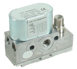
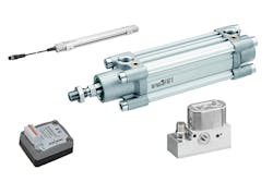
The electropneumatic positioning system (EPPS) uses two proportional pressure regulators mounted on the pneumatic cylinder, one on either side of the cylinder piston. One side maintains a constant pressure using the first proportional pressure regulator (E/P valve), while the second E/P valve controls pressure on the opposite side.
The unit’s electropneumatic positioning controller (EPPC) receives data from and sends analog pressure command signals to the proportional pressure regulators. The controller compares the position command to piston feedback. A proportional-integral-derivative (PID) loop provides an analog output to the second proportional pressure regulator to adjust the pressure as needed. Greater pressure on the second side means the piston will move forward, and vice versa.
Air’s Advantages
While electromechanical and flow-based electropneumatic systems offer effective positioning capabilities, direct proportional pneumatic control systems such as the EPPS hold a number of inherent advantages.
The main advantage of this method is higher accuracy. Proportional pressure regulators constantly and precisely control the pressure, eliminating effects of dithering. The direct-acting pneumatic pressure regulators can control pressure within 0.10 psi, and the EPPS system can use any of the company’s pneumatic actuators. That gives system designers a lot of flexibility.
Note that every actuator has different physical characteristics, so it is difficult to make a broad statement regarding positional accuracy. However, with a properly selected actuator and optimized tuning of the controller, ±1 mm positioning accuracy is certainly possible. This is better than traditional flow controlled pneumatic positioning.
The EPPS is designed to economically deliver the benefits of pneumatic positioning to a broad range of automation applications. The system uses standard, off-the-shelf components which are easy to integrate and can be quickly replaced when needed. The EPPS uses an AVENTICS SM6-AL (Hall Effect) sensor, and does not require the cylinder piston rod to be gundrilled as in traditional pneumatic systems. Eliminating gundrilling lets standard cylinders be used, thus reducing cost and delivery time.
Although it relies on electronic controls, the EPPS does not require complex programming: A user simply inputs an analog position command, saving time and resources. Standard analog command for stroke set-point is 0 to 10 Vdc or 4 to 20 mA.
In general, electropneumatic systems are more durable than electromechanical systems because they do not require electric motors or drives at the actuator. Thus, they can withstand harsher conditions such as temperature extremes, dusty conditions, and wet and dirty environments.
Finally, the EPPS improves positioning accuracy compared to conventional pneumatic positioning, and it eliminates drawbacks (such as dithering) associated with flow-based pneumatic positioners. For many automation applications requiring proven performance, high throughput, and ultraprecise positioning accuracy and control, the EPPS offers a viable alternative to electromechanical and flow-based positioning systems.
Electropneumatics at Work
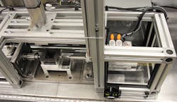
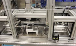
For example, a mechanical-components OEM turned to the EPPS to automate a press that’s used in an assembly process for installing bushings in housings. The press is designed to handle two different sizes of housings. The smaller housing requires two pneumatic cylinders to press two sintered bronze bushings into place, one on each side of the housing. The machine simultaneously installs both bushings in a single operation.
A larger housing requires three bushings to be pressed into place. As with the smaller part, a bushing is pressed into each side of the housing. However, for the larger unit, a second operation is needed to press the third bushing in place inside the housing—a cumbersome and tricky task when performed manually.
To speed the process and improve quality, the manufacturer chose the EPPS system to precisely and quickly press the bushings into the proper positions. The operator selects the required housing size via an HMI; a PLC then sends a command signal to the EPPS controller (EPPC) and on to the electropneumatic control valves, ultimately controlling actuator position during the pressing operation.
The system uses two ED02 electropneumatic pressure-control valves and two PRA pneumatic ISO piston-rod cylinders for pressing, plus a third cylinder for clamping parts in place. In addition, an RTC rodless cylinder opens and closes an operator safety shield.
The OEM automated this process to ensure accurate bushing placement, reduce the cycle time for the operations, and improve operator ergonomics. Results show the bushings are precisely mounted with less effort and fatigue, and cycle times decreased about 30%.
One final note: When designing the automated press, the company’s manufacturing engineers considered an alternative system using an electric servodrive. The EPPS system won out, based on an estimated cost savings of approximately 40%.
This file type includes high resolution graphics and schematics when applicable.


