Automated motion guidance systems with heavy-duty load capacities are experiencing a significant increase in demand. One reason for this revolves around the installation of flexible multi-axis robots onto long tracks. This allows engineers to greatly extend the work envelope while taking full advantage of a robot controller’s seventh axis.
For many applications, a linear motion guided gantry system can accomplish the same tasks as a multi-axis robot while incurring less cost. Additionally, these gantry systems can be designed and supplied to end-users from standard heavy-duty subassemblies or components and can be tailored to the specific application.
Here’s a look at five highly configurable systems that can be used in gantry configurations for factory floor automation in place of sophisticated robots. Let’s start by reviewing some of the basic gantry concepts.
Low to Medium Precision
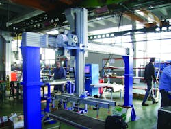
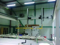
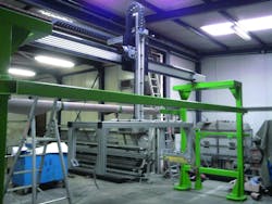
Factory automation does not always require a high degree of precision. In many cases the task involves heavy products and awkwardly shaped or off-balanced materials. Most applications require high repetition, extended operating time, and long-lasting durability with minimal maintenance. Frequently, the requirement for precision positioning is low (Fig. 1).
Pick and place applications can require low precision when palletizing cases or placing the next item into the production queue. Material transfer applications may involve relocating products with an overhead robotic manipulator from one area to another. XYZ gantry robots (the Z-axis refers to the vertical direction) can position and reposition materials anywhere within a three-dimensional space or enable operations on many faces of a work piece. Spraying systems may require low precision over long distances to paint a rail car or airplane wing.
Heavy Duty Z-Axis
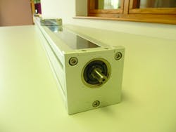
When moving a product, the first order of business is lifting that load. Great care is often taken in the design of end-effector grippers used for manipulating the product. A simple vertical lifting or lowering machine can be referred to a Z-axis system (Fig. 2).
After the item is lifted and supported by the system, all motion will generate additional loads due to accelerations of the mass. Significant loads may be generated during high-speed motion. Speed is typically determined based upon cycle time over the required distance. Loads are calculated based upon the acceleration (+ and -) of the mass.
Speeds in typical gantries extend to 5m/s.
Therefore, a heavy load capacity may be required to accommodate the expected motion. Additionally, a long service life can be designed into the application when working load requirements are a small ratio of the motion systems load capacity.
X-Z Robot or X-Y-Z Cartesian
Single-axis motion stages can be combined with other positioners in various gantry configurations. Attaching additional motion systems adds reach and functionality, and tasks can be performed over longer distances.
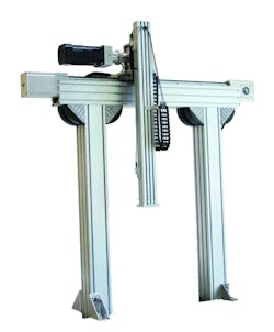
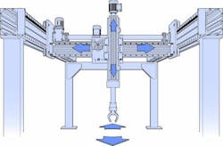
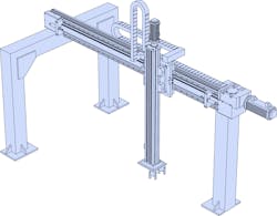
X-Z robot: When a Z-axis linear motion stage is mounted on an additional transverse axis of motion, it can be referred to as an X-Z robot. This configuration can lift an object vertically, move to another location in a straight line, and place the object there. This configuration is particularly useful for pick-and-place or transfer applications. The end of the X-Z robot can position and locate anywhere within a rectangular plane (Fig. 3).
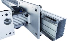
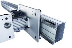
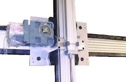
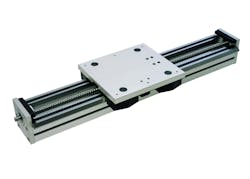
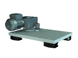
In some cases the main mounting plate for the X-axis can hold the linear guide bearings to the Z-axis and integrate all of the necessary pinion drive and automatic lubricator components. This greatly simplifies the design and reduces the overall moving mass (Fig. 4).
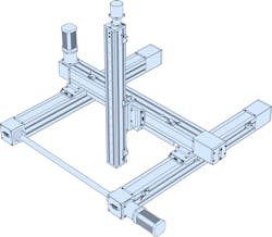
X-Y-Z robot and X-X’-Y-Z robot gantry: The most flexible configuration of a robotic gantry system provides for three axes of motion to enable positioning anywhere within a three-dimensional work area. It is less common to have an X-Y-Z configuration because the axis attachment points become space constrained. However, this configuration is used extensively in automated welding where there are large travel reaches but no major loads. It is much more common to have a parallel X-axis solution where the Y-axis is supported on both ends. This configuration is called an X-X’-Y-Z gantry (pronounced X, X-prime). Examples of this configuration are easy to find in production machinery such as CNC routers (Fig. 5).
Unlimited custom design configurations: There are many possible designs for a large-format automated motion system. A complete multi-axis XYZ gantry robot can be custom designed from the individual linear guide rails and linear bearings, enabling engineers to select the best products for each area of the design.
Existing product lines provide standardized components and subassemblies, which speed configuration and development by using common gantry layouts while providing the freedom to create a custom design. This is not possible with preconfigured or premade equipment that restricts work within previously established limits.
Five Options for Gantry Design
When designing automated machinery it is usually best to start with a complete understanding of the required task and payload, the end-effector grippers that must be attached to the system, and an approximation of both the travel distances and the speeds necessary during the travel. From there, the size and stroke length of the Z-axis can be determined followed by the other axes of travels.
The cantilever axis: A dedicated cantilever axis is a complete subassembly designed with the Z-axis application in mind. Linear actuator modules (those from Bishop-Wisecarver, for example) contain vee guide wheel bearings running on hardened and ground linear guide track with power transmission provided by belts. They are available in a special version as a cantilever axis where the drive belt is stationary on the beam; it follows an omega shape around the motor pulley, which is attached in the middle.
When the motor turns the drive pulley, the beam section of the linear motion stage moves. This in an ideal configuration for the Z-axis of a gantry system because there can be simplified cable routings and the motor does not add to the moving mass.
Another great feature of these actuator types is that the base is fabricated from T-slot aluminum, which can be readily attached to other motion axes or framing members. Although it is useful as a Z-axis linear module, these actuators have limited load capacity due to the belt system and the smaller size of linear bearings. These features make this product ideal for smaller loads and higher speeds, but it should not be considered for heavy loads (Fig. 6).
The ballscrew actuator: Ballscrew driven actuators are another type of complete subassembly for linear motion stages that can be readily attached to other actuators in a variety of useful orientations. They are based upon similar actuator technologies and share the same key advantages, including the t-slot aluminum beam frames, internal linear profile rail bearing, stainless steel cover strips with magnetic seal, internal travel bumpers, and simple gantry system attachment methods. The main difference from the belt-driven cantilever actuators is the use of a ballscrew as the drive technology. It enables the motor to be attached in a linear fashion above the axis and provides substantial, efficient thrust capacities, which are well suited for lifting and lowering heavy loads (Fig. 7).
Ballscrew actuators are available in many standard sizes with beam lengths up to 2,800 mm long. They are available with numerous ballscrew choices in a variety of diameters and lead pitches. A typical ballscrew actuator can handle loads up to 68,000 N radially mounted, but when mounted as a Z-axis it has a maximum torque load capacity of 4215 Nm. Substantial life can be obtained from these product types up to 10,000 km of travel at 360 Nm (Fig. 8).
The heavy-duty ballscrew system: These are preconfigured assemblies of components from a product line of heavy-duty linear guides. The preconfigured actuator system with an integrated ballscrew drive can handle up to 40,000 N radially, or in the gantry Z-axis position 3220 Nm of torque moment load. They use a variety of large aluminum extrusions as the base structure for heavy-duty linear motion and include a wide variety of vee guide wheel bearings and linear guide track rails. These items are available as individual components and subassemblies.
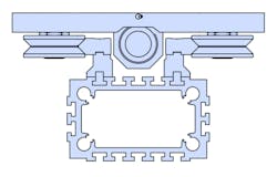
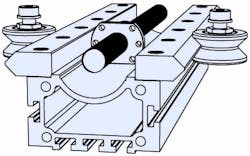
The aluminum beam of the heavy-duty system has many t-slots for attachment points. There are features in the cross-section that can be thread tapped. Complete structures can be fabricated from this large aluminum beam. The vee slide linear track is attached to the aluminum beam base and is supported by an intermediate backplate extrusion. This assembly provides enough clearance for the ballscrew (Fig. 9).
Heavy-duty ballscrew systems are available in standard sizes based upon the outside diameter size of the bearings, as well as different precision grades which includes commercial and precision versions. These grades refer the selection of linear guide track. Both versions are made from high-carbon steel, which is surface hardened for wear resistance. Commercial versions provide good accuracy and are etched on the wheel running surfaces. Precision versions are ground on the vee running surfaces and the mounting face to provide a greater level of accuracy (Fig. 10).
The heavy-duty compact ballscrew system: The heavy-duty compact system is also a preconfigured ballscrew linear actuator. In contrast to the heavy duty ballscrew system, the compact system uses a less gargantuan aluminum extrusion as the actuator base. The vee slide carbon steel linear guide track rail is directly attached to the beam without the need for a track backplate, and there is a recess in the profile shape to accommodate the ballscrew. Therefore, the overall height of the assembly can be significantly reduced. The beams can accommodate the same linear guide track and bearings as the heavy duty ballscrew system (Fig. 11).
Heavy-duty compact ballscrew systems are available in standard sizes. The beam section with track can be up to 2740 mm in length, but in some special cases the length can be as long as 5840 mm. The vee slide components are the same as those used in the heavy-duty ballscrew system, so there are different available grades of precision including commercial and precision versions.
There are also several choices of ballscrew pitches and leads. Because the same vee guide bearings and vee slide linear rails are used, these actuators share similar loading capacities with the heavy duty ballscrew system and the units can accommodate up to 40,000 N radially. When they are used in a Z-axis gantry configuration the load capacity can be up to 1291 Nm (Fig. 12).
The heavy-duty compact ballscrew actuator is an ideal size for most Z-axis vertical lifting operations and easily integrates with other motion stages. It can also be supplied with bellows style way covers to keep debris out of the slideway and ballscrew (Fig. 13).
Customized Z-axis: There are many possible combinations when assembling the standard products into motion stages, and equipment builders have designed numerous variations. Many configurations of standard products that have proven to be suitable for Z-axis motion stages.
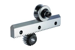
The design starts with the compact aluminum beam used in the compact ballscrew configuration. Although it is labeled as a compact beam, the structure is quite large and suitable for Z-axis applications. Next, vee slide linear guide rails are attached directly to the aluminum beam. A version with machined gear rack teeth is used for the power transmission instead of a ballscrew or belts that the other types of actuators use. Only one of the vee slides requires the gear rack option to drive they actuator (Fig. 14).
There are a few preconfigured carriage plate assemblies with guide wheel bearings and user attachment threads. The designer can select a carriage plate or specify his own design. A complete rack-driven carriage for the application can be supplied to make a complete driven Z-axis for heavy-duty applications.
Benefits of Using Heavy-Duty Components
Aluminum beam construction: T-slot based extruded aluminum beams are an ideal base material for gantry mounted linear motion systems. In many installations the frame can be fabricated out of the same extrusion as the actuator. These materials can be quickly installed with basic tools at the installation location and there are many brackets for attaching the extrusion. Additionally, these materials can be attached to welded steel support structures.
Linear guides with integrated racks. The time savings for using vee slides with the gear rack option cannot be overstated. Aligning a gear rack to a liner stage over a long travel length, in a heavy-duty application, can be a difficult and time-consuming task. Improper alignment will result in premature wear and low operational life. When the gear feature is integral to the vee slide section, the alignment is taken care of because there is only one part to install (Fig. 15).
System maintenance. It is not difficult to obtain the rated service life of a linear system when proper maintenance recommendations are followed. Lubrication is recommended for vee guide wheel linear motion so there are provisions for automatic lubrication. External track lubricators can be added to carriage assemblies or there is the option of adding wheel cap wipers. In some case, a maintenance technician can replace a single wheel bearing without a complete disassembly of the motion axis, and without removal of the cap wiper.
Load capacity and expected life. These products are capable of high loading conditions and can perform well in high-speed, high-cycle applications. Each design is validated with an expected life calculation so that the durability of the system is determined early in the design phase. If additional life is required, there is always the option for increasing the load capacity. Capacity is limited by the load rating of the bearings, along with the physical construction of the bearings. You could use larger bearings with more capacity or change to a different type of bearing (e.g., going from a ball bearing to a roller bearing).
These five products are a small sample of the wide range of heavy-duty products that are available. However, the majority of Z-axis and multi-axis gantry applications would be satisfied by these recommend solutions. These products should be considered as a viable alternative for track-driven robots and gantry motion applications.
