Six keys to more-precise linear motion
Armed with even with the most-sophisticated motion controller, engineers can still find it difficult to attain precise linear motion unless the mechanical components are appropriately designed for the application. Granted, different markets have varying definitions of precision, from nanoscale levels in the semiconductor industry to the relatively generous 0.01-in. standards seen in packaging or newspaper printing. So the industry and application usually determine the needed level of precision. It’s also important to know the operating environment, because some environments make it more challenging to hit the required target.
Let’s start by considering how to define precision. Precision is a combination of accuracy and repeatability. Accuracy, the discrepancy between a movement’s target position and the actual position, reflects motion targets being approached from different directions (multidirectional). So positioning accuracy is the maximum deviation between the actual and target positions during each motion. Repeatability relates to how precisely a linear-motion system positions itself when repeatedly approaching a position from the same direction, taking into account deviations in actual position from the target position. Engineers can improve these parameters by focusing on the following six areas.
Travel accuracy
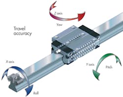
Travel accuracy measures pitching (up and down), yawing (side to side), and rolling (around the axis). Minimizing these motions depends on the quality of the travel guidance system and the surface it mounts on. Linear-motion systems typically conform to their mounting surfaces, so travel accuracy varies with machine surface alignment, preparation, and tolerances.
High-quality travel-guidance systems follow industry standard tolerances for height, width, and parallelism. For example, Bosch Rexroth, Charlotte, N.â C., offers products covering a range of six accuracies, from N (Normal Precision) height/width tolerances of ±100 μm/±40 μm to UP (Ultra Precision) height/width tolerances of ±5 μm. Keep in mind that as the tolerance band decreases, component costs increase. Spending more on components and not addressing the structural elements’ flatness and straightness wastes money and diminishes travel accuracy for the axis and machine.
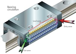
Also, bearings circulating inside a linear guide can cause precision-reducing vibration as the bearings transition from “load-bearing” to “nonload-bearing” conditions. Some manufacturers optimize the bearings’ transition-point geometry with specialized high-precision runner blocks to minimize vibrations. For example, Bosch Rexroth’s High-Precision ball rail uses a steel insert with relief zones that dampen ball-entry forces at the ends of the raceway. The result is consistent, extremely smooth motion as balls circulate in the bearing raceways.
Positioning accuracy depends on the capabilities and tolerances of the drive, such as an electromechanical ball screw, hydraulic or pneumatic cylinder, electric linear motor, or rack and pinion, among others.
Ball screws can have significant lead error or lead deviation within the ball screw or ball nut — the element typically connected to and driving the load. The degree of error often depends on the manufacturing method used to generate the screw threads. Grinding can introduce lead error from the inherent machine inaccuracies, tool wear, or heating of the ball-screw shaft during the grinding process. Forming threads via rolling can introduce lead error primarily through the postprocess heat treatment.
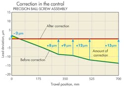
Grinding has traditionally been recognized as more accurate than rolling, but the gap is narrowing. Some Rexroth rolled screws deliver Class 5 or even Class 3 precision for travel (lead) deviation, with a maximum deviation of ±12 μm across 300 mm of travel. Electronic correction techniques, which compensate for small lead errors across standard travel runs, can further improve accuracy. The “Correction in the Control” graphic shows a corrected lead deviation of up to 13 μm across 700 mm of travel.
Adding external feedback to the machine axis can also improve positioning accuracy. This can be done indirectly using a rotary encoder or directly using a linear scale. One example, Bosch Rexroth’s IMS (Integrated Measuring System), integrates a scale into the guide rail and a sensor head on the bearing block. Positional feedback from the sensor lets the servodrive correct the final motion position.
System stiffness
This is an area where mechanical factors often reduce the efficiency of the finest controls. The machine’s frame and base rigidity, thickness, material (for instance, aluminum versus steel), and frame construction (solid or tubular) can all have an impact on precision. Mechanical-drive-based factors such as preload, axis length, types of antifriction elements and bearing support, as well as the fasteners connecting the linear-motion system to the frame can all indirectly influence machine precision.
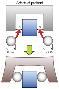
System stiffness is critical because any force or load applied to the motion components — downward, upward, or sideways — can cause deflection, an enemy of repeatability. Greater force produces more deflection. To combat this, designers often improve the overall rigidity or stiffness of the linear-guide block by introducing preload with oversized antifriction elements. The “Affects of Preload” graphic shows a typical preload, using oversized rolling elements (Dk) in the guide-rail gap (diameter D). Linear-guide manufacturers typically offer widely varying levels of preload to minimize deflection.
The drive can contribute to total system rigidity through the stiffness of its support bearings, ball-nut unit, and the ball screw itself. The biggest factor affecting the stiffness of the screw drive is its length: the longer the screw, the harder it is to compensate for deflection. Compensation techniques include extra preload or selecting a stiffer ball nut.
Demanding, high-throughput applications present tough challenges because short cycle times sometimes have speed requirements that tax the limits of linear-guide and ball-screw speed and acceleration capabilities.
The first limit is the ball-screw shaft’s critical speed — the speed at which the screw vibrates or oscillates excessively (known as screw whip). This speed depends largely on the shaft length and bearing supports. The ability of designers to alter critical speed is limited mainly to the choice of end-bearing supports. Fixed-fixed mountings (where bearing are constrained at both ends of the screw) allow the highest critical speeds, and fixed-free systems, the lowest.
With a fixed mounting, the bearing arrangement is truly fixed on the screw and has a bearing set designed to support axial loading. Floating mountings may be chosen because they introduce less friction, allowing better thermal performance, but they have a lower critical speed than fixed mountings. Floating mountings typically use just a radial bearing to support the radial load or weight of the screw out in space. This arrangement gets its floating name as the bearing is allowed to float or move in the pillow-block housing as the screw spindle expands and contracts due to temperature changes.
The second limitation is the bearing system’s characteristic speed, based on the circulation of antifriction elements. In the case of a ball screw, the ball nut represents the bearing system. Temperature, vibration, and inertia of the balls all play a role. The characteristic speed is often called the Dn factor, calculated by:
d0 × n ≤ Dn
where d0 = ball-screw nominal diameter (mm) and n = speed in rpm.
The lower of the two speeds is most critical for precise motion control. Characteristic speed is independent of shaft length, but critical speed declines as length increases. When a system reaches critical speed, vibration increases, accuracy drops, and performance (for example, machining surface-finish quality in a machine tool) will diminish. In addition, the ball-screw assembly will fatigue much faster.
Thermal considerations
All linear-motion components (motor, bearings, and nut) generate heat that must be accounted for; proper management of these thermal influences can improve the performance and precision of a system. Different parts of an axis can have different temperatures based on running time, dynamic cycle, and forces on each part. Letting bearings float within a pillow block allows for ball-screw expansion and contraction, but a trade-off is that they are less rigid. Using a combination of fixed bearings, or bearings capable of supporting axial/thrust loads, and floating pillow blocks with radial bearings gives thermal flexibility while improving speed characteristics.
Thermoelastic deformation presents another challenge for engineers, as heat influences linear expansion of all components. Deformation could cause misalignment or displacement, which puts excess force on the bearings and nuts. This force creates friction, which leads to even more heat generation. The higher the rigidity an application requires, the more friction-generated heat will affect alignment, stiffness, and performance. The good news is that with advances in drive and control electronics, designers can often offset or compensate for these thermal influences.
Machine resonance
All of the above factors can make machines resonate or vibrate, which compromises precision and quality. In extreme cases, vibration — such as that produced by exceeding critical speed — can cause “whipping” of the screw, and machine damage. Other possible causes of vibration include:
- Excessive run-out or improper concentric rotational screw behavior in relation to the center axis of the ball screw spindle, drive journal, or other component.
- Excessive backlash.
- External influences (resonance from nearby machines, forklifts, the HVAC system, and so on). This is often overlooked. It can be counteracted by mounting the machine on a special, isolated foundation pad.
Design decision-making
In some markets, greater precision may not justify spending substantial resources for minor improvements — but then again, it may help differentiate a new product. Also keep in mind the level of precision called for by the standards and necessities of the market.
In a particular application, extremely high throughput requirements may also limit precision. And the need for quick changeover times may require some trade-offs in precision to attain a simpler design.
Finally, consider emerging market requirements, particularly in the areas of energy consumption and lean manufacturing. Improved precision may significantly reduce waste and rejected parts, adding yet another element to the benefits of more-precise linear-motion systems.
