Advancing Toward Safer Automation Design
Since the 1970s, safety has been a part of automation and motion control. The problem has always been that many safety regulations are out of date and safety methods resulted in basic “stop” or “lockout” functions that would halt production.
A “Survey of Occupational Injuries and Illnesses” conducted by the U.S. Bureau of Labor Statistics highlighted that in 2013, private industry employers reported a little more than 3.0 million nonfatal workplace injuries and illnesses. That’s an incidence rate of 3.3 cases per 100 equivalent full-time workers.
Nonetheless, in the last decade, many changes have been implemented to improve and better integrate safety. This includes a raised focus on safety analysis and smart products that make it essentially harmless to incorporate safety methods.
Machine Safety Standards
In the United States, the Occupational Safety and Health Administration (OSHA) and the National Fire Protection Association (NFPA) administer machine safety standards. Overseas in Europe, the International Electrotechnical Commission (IEC) and the International Organization for Standardization (ISO) are used as the barometer for regulation standards, which are applied at a global level for other countries like China, India, and the U.S.
The multitude of agencies and standards may confuse machine builders and engineers in cases where hardware can fall under more than one standard. If an injury occurs within the U.S., would OSHA investigate and inquire if the machine was as safe as possible? Prior to 2012, a programmable logic controller (PLC) could be built to comply with the European Union’s Machinery Directive (EN/ISO 13849-1) but not comply with the NFPA 79, the U.S. equivalent that addresses safety-rated PLC and safety buses. This muddies the waters for engineers trying to build devices that follow the proper safety regulation.
Another hindrance is the current state of safety regulation. Since the 1970s, machine safety standards have been slow and not kept up with the technology. Before 2002, all hardwired components were required to use emergency stop pushbuttons. This diminished the flexibility to reduce production downtime; it was not until after 2002 that users were allowed to use safety PLCs and software-based controllers.
Similar problems were occurring in Europe, as the EN 954-1 safety standard did not cover programmable electronic safety equipment or failure probabilities as far back as 2009. In 2011, the EN ISO 13849-1 and EN 62061 replaced the EN954-1 that covered all machine and process safety systems sold within Europe.
In the last 10 years, we are seeing safety-standard updates being applied to all major manufacturing countries. Sean O’Grady, a Product Manager of Valve Terminals and Electronics from Festo, says that “Globally, many countries and industries have taken advantage of the groundwork created by the European Union (EU) machine directive of 2006. For instance, EN ISO 12100 covers general principle of design for machinery safety, while EN ISO 13849-1 deals specifically with safety-related parts of control systems. Within the U.S., for example, various regulations and industry standards reference these documents directly.”
EN ISO 13849-1, for instance, applies to many technologies, including electrical, pneumatic, hydraulic, and mechanical. This standard provides requirements for the design and integration of safety-related parts of control systems, including some software aspects of safety-related systems. It can also be applied down to the component-parts level of the system.
Designing with Safety Programs
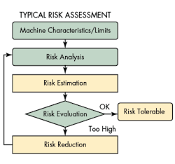
With new standards come new procedures. Risk assessment, formerly known as hazard analysis, is the process of identifying a risk (or hazard identification), risk estimation, and developing a risk-mitigating protective measure. Risk assessment is the basis for defining machine safety. The definition of risk assessment has been added to ISO standard 12100, and is included in other international and regional standards such as IEC61508, IEC61511, and IEC62061.
To help mitigate risks, companies should be using safety programs to identify and solve possible risk situations. These risks can not only harm human beings physically, but may also affect revenue and/or earnings. Manufacturing institutes several safety programs:
• Occupational Safety and Health: Employee training and education of safety procedures and proper machine use
• Product Safety: Safety warnings for proper use, machinery, and equipment repair maintenance
• Machine Safety and Safeguarding: Physical safeguarding, safeguard controls, and safe work procedures
• Environmental Safety: Clean-up procedures and proper containment requirements to avoid air and ground contamination
• Property and Equipment Safety: Systems that protect capital investments like automated sprinkler systems
Safety programs are comprised of risk analysis, risk-mitigation measures, and training/supervision related to work procedures. Risk analysis is the first step in which two quantities are measured: the magnitude of potential loss and the probability that loss may happen.
To effectively identify a risk, one analyzes the employee activities and the potential risks they may encounter through defined work practices, or the potential risks that employees can introduce due to lack of training or experience. Risk analysis should also identify risks caused by potential environmental exposure, limited safety protection measures, improper installation, or equipment failures. Not only are these risks inherent to workers, but also to plant equipment and the environment.
The process defined by these standards is one of a lifecycle approach on how to implement an effective process to identify and quantify machinery-related risks. The risk is quantifiable in terms of severity, frequency of exposure, and probability of avoidance. To lower the quantified level of risk, one implements protective measures.
Protective measures represent any act that lowers the level of risk. This can be done by eliminating the risk through a better design, using physical guards, including engineering controls like light curtains or safety PLCs, and providing better training and procedures. These protective measures should be documented and their effectiveness recorded for future evaluations. Using documentation in the risk-assessment process is critical so that companies are able to show their due diligence and best engineering practices.
After implementing protective measures and proper documentation, the next step is training and supervision. All operators require proper training to effectively use the machines and perform their tasks safely. The tasks and roles of the operators should be clearly defined, along with having full knowledge of their processes.
Safety Programs and Common Terms
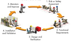
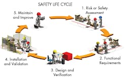
One example of a safety program is Rockwell Automation’s Safety Life Cycle. Rockwell Automation utilizes different safety methods and procedures to help reduce the time to design and develop safety solutions. The Safety Life Cycle improves safety by identifying the steps required to properly assess and mitigate any risks.
The first step is to perform a hazard or risk assessment by identifying hazards and estimating their associated risks. The next step is determining the functional safety system requirements, which involves evaluating safeguard options based on industry standards. Following that comes design and verification of the system. Designing systems includes planning the system architecture, document safety circuit design, and procure the appropriate materials.
Once the design is complete, the next task is to install and validate the system. This involves operating the system, ensuring that it responds correctly to failures and safeguards are in place. Once verified, the last step is to maintain and improve the system. Continued monitoring and recording of the system’s performance is essential so that the results can then be integrated back into the top of the lifecycle for a better risk assessment.
Designing safety programs that adhere to new safety standards also typically involves having to learn new terms. According to Duško MarkoviÄ, Manager of Application & Specification, and Dr. Carsten Springhorn, Quality Manager, from Aventics, “If safety of a machine depends on a correct function of the control system, it is called “functional safety” with special requirements on the availability of the safety function. In functional safety, the main focus is on “active” parts of the control system, meaning components of control systems responsible for identifying a dangerous situation (input/sensors), deriving the suitable reactions (logic), and implementing these measures in a reliable form (output/actuators).”
Festo Corp. has listed some common terms that design personnel should get to know in order to comply with the new standards:
• B10D: The number of switching operations at which 10% of samples fail. This value is required to calculate the overall performance for a safety circuit. It only applies to the dangerous failures and is given over a lifetime of 10 years.
• CCF: Common cause failure is generally the single failure or condition that affects the operation of multiple devices. Normally this would be considered an independent failure—isolated to an individual part or process. In reality, it can have a domino-like effect that will affect other subsystems or parts.
• DC: Diagnostic coverage involves the combination of hardware, software, and testing of related diagnostics. It is the ratio between the probability of detected dangerous failures and the probability of all dangerous failures.
• DCavg: The average diagnostic coverage for a system or component.
• SRP/CS: Safety related parts of a control system refers to all safety-related control elements regardless of the type of technology: electrical, hydraulic, pneumatic, etc. It does not specify safety functions or performance levels.
• Designated architecture: The predetermined structure of an SRP/CS. Choosing a system architecture is one of the first steps of the safety program.
• MTBF: Mean time between failures indicates the mean time between two failures for a particular component.
• MTTFd: Mean time to fail is the mean time between two dangerous failures.
• PFH: Probability of failure per hour is the probability of a failure per hour for that component to assist in detecting random hardware safety integrity.
• PFHd: This represents the probability failure per hour for dangerous failures for that component to help detect random hardware safety integrity.
• PL: Performance level of the SRP/CS to operate a safety function and to reliably achieve it.
• PLr: The performance level required is the goal for designing the actual safety circuit. The result of determining the designated architecture is in part to determine the required performance level of a safety function.
• SIL: Safety integrity level is a common term used by safety component and device manufacturers when designing safety systems and circuits.
Modern Safety Technology
According to Kyle Hall, Product Engineer of Fieldbus Technology for Turck, the greatest challenge in implementing new safety programs is to “get customers onboard with the safety assessment and validation procedures.” The problem is a familiar one: Fear over implementing new standards and systems into current architectures. However, new technology and products are now being designed with safety in mind.
Modern advances into safety have helped ease the installation of safety programs by integrating safety functions into their products. Jim Grosskreuz, Product Manager for Rockwell Automation, speaks to how “safety is becoming a core function of motion control.” This is evident in Rockwell’s product line, which includes the PowerFlex 750 series with safe-speed motion monitoring. Three stages of safe-speed monitoring allow for better operation of servos:
1. Safe direction: Configured to monitor the safe direction, a shutdown occurs if the motor attempts to rotate in the dangerous direction.
2. Safe limited speed: The safe-speed module initiates a shutdown if the motor exceeds a pre-determined speed (the safe max speed). It then ramps down to a safe speed and the maintenance door control logic is set to unlock. This enables access to the machine for cleaning or clearing. A risk assessment is needed to determine the safe maximum speed for the axis.
3. Standstill (zero) speed: The safe-speed module initiates a safe stop upon deactivation of the inputs. Standstill speed is used to declare motion as stopped. The system is at standstill when the speed detected is less than or equal to the configured standstill speed. The door control logic is set to unlock when standstill has been reached.
This control logic allows for safe access and maintenance to the machine, but does not stop production. This reduces downtime by 60 to 70%.
Festo, for instance, integrated safe inputs and outputs directly into its pneumatic-valve terminals. In the past, a machine designer would need to specify an appropriate safety relay or safe output, and perform all of the required safety calculation and documentation. The designer would then have to manage the proper installation, commissioning, verification, and validation of the resulting safety function to ensure proper function and legal compliance. By selecting an integrated solution, time and effort is reduced while also providing the designer with additional diagnostic capabilities and more complete documentation, which facilitates legal compliance.
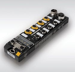
Ethernet connections offer new ways of connecting machines to safety devices that can regulate other devices. An example would be the TBPN Ethernet hybrid input/output (I/O) safety block developed by Turck. The block can execute safety functions locally or exchange safety I/O with a variety of controllers. On the safety side of the PROFIsafe/PROFINET module, the user has two safety inputs to connect different safety sensors, such as light curtains or emergency-stop buttons. Two additional safety channels can be used either as inputs or bipolar outputs.
Two of the I/Os can also be connected as IO-Link masters. When combined with Turck's I/O hubs, users can connect up to 32 additional I/Os to the module. The non-safety digital I/O as well as one of the IO-Link ports can be safely switched off by internal safety circuits.
These products are designed in accordance with the latest safety regulations. Recent changes in standards allow safety regulations to be applied internationally, and they have been updated to include the latest technology advances. Such product advances now make integrating safety an afterthought.
Looking for parts? Go to SourceESB.
This file type includes high-resolution graphics and schematics when applicable.


