What to Look for When Choosing Holding Brakes
This file type includes high-resolution graphics and schematics when applicable.
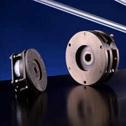
Simply put, holding brakes hold rotating equipment in place: If rotation is not desired, a brake can be applied. Many industries have holding-brake applications—factory automation, medical equipment, elevators and escalators, construction equipment, robotics, machine tool equipment. With so many applications and different designs available, it may be tough pinpoint the correct holding brake. This article will walk you through properties and considerations to help ease that decision.
The majority of brakes available today are spring-applied brakes. In other words, they generate their holding torque by utilizing a spring mechanism to apply pressure to a friction surface. These brakes are disengaged by releasing the pressure of those springs via hydraulic, pneumatic, or electromagnetic actuation.
Another type of holding brake, called a permanent-magnet brake, operates a little differently as it doesn’t use a spring mechanism at all. Rather, it relies on the force of permanent magnets to apply pressure to the friction surface. These brakes are disengaged by canceling out the permanent-magnet field, which is achieved by applying voltage/current to the brake’s coil to create magnetic flux.
Torque
The first step in choosing an appropriate brake is to determine the torque required in the application. Usually somewhere under 20,000 lb-ft, electric spring-set brakes become an option. They are often the preferred choice for lower-torque applications because cost is a main driver. For higher-torque applications, hydraulic and pneumatic brakes are often better suited.
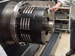
Hydraulic and pneumatic holding brakes can easily achieve 20,000 to 500,000 lb-ft in torque. These large brakes can be either multiple-disc-style or caliper-disc-style brakes. Pneumatic or hydraulic brakes tend to be better for stopping high-inertia loads. Many times they have replaceable friction discs and can be serviced. Because their power is easier to control, they can give a softer stop in high-load applications such as amusement park rides.
Deactivation Source Availability
The next step is to determine the types of deactivation options at hand. Is there a hydraulic or pneumatic source available, and does it have the pressure required to release the brake? You have to consider your application environment and facilities.
For example, construction elevators or hoists are not going to have pneumatic or hydraulic lines running up and down them, so electricity is a better option. Conversely, small elevators of two and three stories typically use hydraulic and pneumatic brakes because of the resource availability. Typically, electric is always available because even with hydraulic and pneumatic applications, an electromechanical valve is required to control the deactivation source.
Stop and Hold (Cycle) or Hold Only
A considerable difference can exist between a holding brake required to stop and hold the load versus hold only. The concern is energy per engagement. The energy absorbed per brake engagement determines how much wear will take place, and therefore determines the brake’s overall lifecycle. The energy formula is modified from:
E = (1/2)mv2
to
Ee = (M*v2*td)/[182*(td+tl)]
where Ee = energy per engagement; M = inertia; v = speed; td = dynamic torque; and tl=load torque.
Then we use the energy per engagement and put that into the cycle formula:
L = v/Ee*w
where L = life in cycles; v = total engagement area; and w = wear rate.
Increasing the wear area, either by diameter or by the number of discs, will increase total life. Also, from either formula, a boost in speed can exponentially increase the energy generated. If the speed or cycle rate is too high, the brake will not be able to dissipate the heat that it generates.
A larger brake would help dissipate heat energy, but sometimes the time at which the brake engages should change. For example, using the motor to slow the load before engaging the brake will reduce the speed which, from the formula, will exponentially reduce the amount of energy the brake needs to stop.
Once the inertia is calculated, along with the operational speed and the required time to stop, it’s then possible to calculate the brake’s total life. If inertia, speed, or cycle requirements are high, you may have to choose a brake with a larger torque rating in order to provide the required cycle life.
For brakes that are holding-only, the calculation is much simpler. We focus strictly on the torque required to hold when the machine is stationary. A good rule of thumb is that the torque required to hold the load would be less than the motor torque required to accelerate the load. This is because in a static state, the friction of the system helps keep the component stationary. So, as long as additional loading does not occur after the rotation stops, the usual sizing of the brake based on the motor’s torque will meet most requirements—assuming that the brake is mounted on the motor shaft.
In some emergency applications, holding-only brakes may be required to perform an emergency-stop function. Holding-only brakes can only do this a small number of times, because they can’t absorb the energy of an e-stop without causing damage or accelerated wear of the friction surfaces. In general, a holding-only brake would be around half the physical size of a stop-and-hold brake.
Speed
For a stop-and-hold application, the inertia caused by the brake is decelerating, along with the speed, determines how much energy is generated per engagement. In holding-only applications, speed remains an important factor. It is not for energy calculation, but to see if the brake disc can withstand the running speed of the application. Some high-speed motor applications can rotate over 10,000 rpm; therefore, the rotating disc in the brake must be able to withstand that speed.
Size
Although hydraulic and pneumatic brakes can provide a very healthy torque-to size-ratio, that benefit diminishes when used in lower-torque applications. In such applications, electromagnetic brakes become the better choice. The electromagnetic brake family offers two options: the traditional spring-applied brake and the permanent-magnet brake. Both can have stop and hold designs.
Advantages with spring-set brakes include:
• Lower cost
• No specialized control needs
• Less sensitive to temperature
Advantages for permanent-magnet brakes include:
• Smaller size-to-torque ratio
• The applied holding force can be controlled to produce a soft stop
Backlash
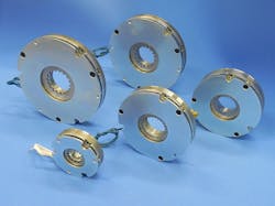
Backlash in an electromagnetic brake is the amount of movement that takes place between the brake hub and friction disc. The hub, which is usually a separate square or a splined piece, allows the friction disc to move back and forth axially during engagement and release. In the larger spring-set brakes, backlash is generally not a concern. However, in lower-torque systems that require exact positioning, backlash becomes an issue.
Multiple-disc brakes have to move on a spline, so they cannot be zero backlash. Caliper discs are also difficult because, although the disc can be permanently fixed to a shaft, the caliper housing is typically on pins that need to have slight axial and radial movement. Again, some backlash develops between those components. Perhaps a better way to explain backlash is that it’s the amount of radial movement measured between the shaft and the brake housing when the brake is stationary and engaged.
Zero-backlash brakes can be required in high-precision automation applications. If the machine has an emergency shutdown during a process cycle, registration and location are not lost and the machine can resume its function upon startup. Many electromagnetic brakes, and some pneumatic brakes, have zero-backlash options.
Environment
Shielding brakes against contamination from lubricants is important in all applications. Larger hydraulic and pneumatic brakes can operate in outside environments. Most standard brakes aren’t sealed, so they need to be encased in some type of housing or covering to prevent contamination.
However, certain special brakes are designed to be completely sealed. In factory-automation or machine-tool applications, the brake needs to be sealed to prevent the oil mist from contaminating the friction surface. If using electromagnetic holding brakes in outside environments, such as golf carts, sealing the brake is necessary to prevent the friction material from absorbing water. If contaminated, some friction material can swell, causing drag in the system.
Most brakes can be designed to operate over a very wide temperature range. Electromagnetic spring-set brakes are commonly mounted to the back of motors. Therefore, the magnet wire in the brake needs to have an insulation class rating that’s high enough to withstand the motor’s high operating temperatures.
Power Requirements
Hydraulic and pneumatic spring-set brakes need a constant pressure to release the springs. Electromagnetic brakes normally operate using a 24- or 90-V dc coil. When the brake is disengaged, the hydraulic or pneumatic pressure is continuously applied or the electromagnetic coil is continuously powered.
For machines using electromagnetic power off brakes in which power consumption is a concern, voltage/current to the brake coil can be reduced after attracting the brake’s pressure plate. Most of the force in releasing the electromagnetic brake is in attracting the pressure plate and compressing the springs. Once the pressure plate is fully attracted to the coil, it takes much less of the magnetic field to hold it in place. Depending on the size of the brake, it could be up to half the normal power requirement.
Machinery manufacturers can program in a lower holding voltage to reduce overall power consumption of the machine. Some brake manufacturers offer separate brake controls with a control that automatically reduces power to the brake.
Response Time/Controllability
Controlling the pressure in pneumatic and hydraulic brakes is relatively easy. Therefore, controlling the applied braking force can be easy, and it’s possible to adjust the stopping time so that the machine or machine’s products are not damaged by a harsh stop.
With electromagnetic spring-set holding brakes, there aren’t many things that can be done to modify the response time. However, a couple of tricks could be applied in this scenario. A faster release time can be accomplished with an over-excitation control, which momentarily applies a high voltage to the coil to rapidly increase the buildup of the magnetic field. A Zener diode circuit can be used To accelerate the magnetic field’s collapse for quicker brake-engagement (Zener diodes allow normal electric flow; however, upon reaching the “Zener voltage,” they permit the electric current to flow in reverse).
Permanent-magnet holding brakes are able to control the opposing magnetic field so that you can control the braking torque to a softer stop. This is important for applications such as conveyors moving sensitive products, or for people riding on escalators or moving sidewalks.
Focus on Electromagnetic Brakes
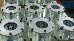
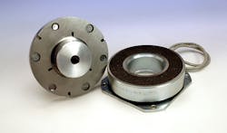
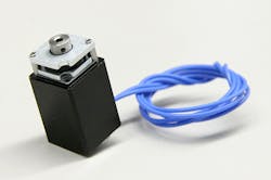
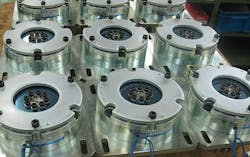
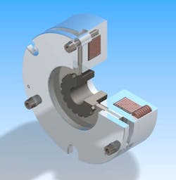
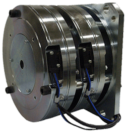
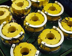
Electromagnetic holding brakes have a field coil, a series of springs, pressure plate, friction disc, and outer cover plate. The brake is engaged mechanically by the springs pushing on the pressure plate to squeeze the friction disc to the cover plate. Turning the brake on and off is done by applying the rated voltage to the coil, which is typically 24 or 90 V.
Permanent-magnet brakes operate via a series of permanent magnets that apply magnetic flux to the friction plate at all times. To release the brake, current/voltage is applied and the opposing magnetic field cancels out the magnetic field of the permanent magnets, allowing the brake to release. Since temperature can influence the disengagement of a permanent-magnet brake, it is recommended to use a constant-current power supply.
Industry Requirements
Each industry has its own requirements when it comes to holding brakes. Customization of electromagnetic brakes over the years has helped the following industries meet those needs.
Elevator/escalator
The elevator industry requires redundant braking in many applications. This can include dual systems, dual brakes, or dual split-plate brakes. In addition, sensors must be incorporated into the brakes, according to European standard EN71 and U.S. standard ASME A17.1 for elevator and escalator brakes. They can be proximity sensors, which make sure the brake is actually engaged or disengaged, and/or thermal sensors that measure temperature to see if a brake is becoming overloaded or if something dragging in the system is generating heat.
Medical
Most machines (e.g., x-ray, scanners, or patient tables) operate in a very quiet environment. Even the click of a brake engaging or disengaging can be objectionable. Therefore, sound-absorbing materials are used. Sound-dampening plastic sheets can be built into the pressure plate to also help deaden sound. In addition, placing plastic sleeves over the standoffs in the brake helps reduce the vibration or rattle of a pressure plate when the brake is disengaged. For motorized wheelchairs or scooters, mechanical release mechanisms are required so that patients can still be moved in case of an electrical failure.
Robotics and servo motors
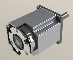
The challenge with robotics and servo motors is always to make the brakes thinner to reduce the overall package size. A lot of work has been done over the past few years to reduce the size of the holding brakes while still keeping the previous torque ratings. Some servo-motor manufacturers have actually incorporated parts of the brake construction into the motor housing, reducing the overall system length even further. Sizes of standalone brakes have shrunk by 30%.
Exact positioning requires a zero-backlash armature design. However, in installations where it is not required, minimal-backlash options can be used, which are less expensive than the zero-backlash version.
Automotive/transportation
Holding brakes used in these applications must accommodate very wide temperature ranges, heavy vibration, and low holding power requirements. The main things automotive companies look for are reputation for quality, actual experience, quality certifications, production capacity, and cost. Engineers look for adaptability to their design.
It is normal for automotive brake applications to be customized. Often companies ask to build custom brakes into some type of motor housing. In this industry, a custom brake can just about become a subassembly of the component it is going into, whether it is on the engine, transmission, differential, or liftgate application.
Stage and screen
Like medical applications, brakes in this industry need to operate very quietly. Dampeners, different friction materials, and sound-absorbing materials are used in the pressure plate of the brake to soften the engagement sound.
In the stage and screen industry, brakes are used to move the stage in place; opening and closing curtains, and most often on the sets and backdrops that are raised and lowered in stage productions. When sets get lifted up off the stage, they are held in place up high out of the view of the audience by the holding brakes. Size as well as sound is important for these brakes, because many times they are fitting a number of motors/reducer winches in line to handle multiple sets.
Frank Flemming is President of Ogura Industrial Corp., which has been making holding brakes for almost 50 years. He has been involved with clutches and brakes for 37 years, starting as a Sales Engineer with Dana Corp. and then moving on to Warner Electric, before joining Ogura.
Looking for parts? Go to SourceESB.
This file type includes high-resolution graphics and schematics when applicable.
