Movable shim stack for high-resolution lifts
What Philip Studer and M. Bruce Millam came up with at the Center in Greenbelt, Md. might best be described as a variable shim pack of constant height. Sounds odd, but imagine a stack of ten poker chips, each 0.1 in. thick, sitting on a table. Imagine, too, a playing card inserted between the fifth and sixth chips. It is 0.5 in. above the table. Now take a chip from the partial stack above the card and insert it in the partial stack below. The card is now 0.6 in. above the table, but the stack is still 1.0 in. tall.
Now replace the stack of chips with a coil consisting of ten turns of 0.1-in.-thick flat material, looking rather like a stiff “Slinky” toy. Imagine further that same playing card between the fifth and sixth coils, that is, 0.5 in. above the table. Now turn the coil one full revolution so that the card rises, while you hold the card so that it cannot rotate with the coil. Now the card is 0.6 in. above the table. You have moved one “chip” from the upper partial stack to the lower partial stack. Had you turned the coil only half a turn, the card would be 0.55 in. above the table. And had you turned it say, 1 deg, think of the resolution in the conversion from rotary to linear motion!
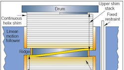
Most applications require thrust considerably more than that needed to lift a playing card, regardless of suit and value. And the card itself isn’t thick enough or of material inherently strong enough to support a useful load. For a practical type of actuator idea, the NASA inventors came up with the device in the illustration.
A continuous helix made, in effect, by coiling a constant-thickness strip (shim), mounts on a drum or spool with axis concentric with the helix axis. The spool can be driven while supported on a fixed base. A follower surrounds the spool and helix and has an internal ridge inserted in the helix to spread the coil apart at one turn, making an upper and a lower “shim stack.” A gap in the ridge allows the strip to remain continuous from the upper to the lower stack. This gap is called the “transition area”. It lets the helix “transition” from the top of the ridge to the bottom, or conversely. For example, the upper shim stack “transitions” to the lower shim stack when the helix turns clockwise viewed from the top; the lower transitions to the upper when helix motion is counterclockwise.
Threadless concept cuts shear stress
The actuator’s thrust load, imposed on the linear-motion follower, takes a path in compression within the follower; in shear from the follower body to its ridge; in compression through the lower shim stack; in shear across the drum lower flange; in compression (thrust) through the bearing; and in compression in the base. In most typical nut-to-thread actuators, the screw thrust puts the screw body in compression — and most metals resist compressive stress very well. However, in such actuators, the shear area across the thread base is the controlling factor for thrust load, both because of limitations in thread size (root thickness), and because most metals are poorest in supporting shear stress.
The inventors note that their device lets the ridge be thick; that is, have high shear area. Likewise for the drum flange. The only penalties are the added thickness increasing the overall height in direct proportion, and the added assembly mass. Elsewhere, pure compression resists the thrust.
The inventors are quick to point out that you could add rolling elements such as balls in more than one way to avoid the pure sliding motion where the ridge meets the helix’s flat surface in the illustration. And they point to perhaps the biggest advantage of all — the high resolution produced by the very small helix angle. The minimum helix angle is controlled by the minimum thickness of the shim; that is, of a helix turn. That very small helix angle also precludes backdriving of a stopped system during vibration, the inventors claim.
They also expect that the device could be built inexpensively because, for example, the helix can be made from flattened roll-formed wire which is “...an inexpensive, high-production process yielding better surface properties in terms of strength and fatigue resistance.” Not specifically addressed are means of restraining the helix so it can’t twist down upon itself, and the thickness-to-transition- gap dimension ratios possible without overstressing the shim in bending during transition.
To dig deeper
NASA owns the invention described here, and a patent has been applied for. Should you want information on licensing, contact the Patent Counsel at Goddard Space Flight Center. A more complete description of the invention is in NASA Technical Support Package GSC- 13141.
Another device using a coiled shim approach is already in commercial production. In it, the coil does not rotate. The “follower” does, and as it does so, it spreads open the flat coil between two successive turns, and a mainspring-like coil is inserted within the turns of the flat coil, in effect, building a large-diameter, thin-wall cylinder. See PTD, “Mainspring and ‘Slinky’ Idea Serves Lifts in Playhouse or Plant,” 8/92.
