Moving Motors Stretch the Possibilities of Long-Travel Motion
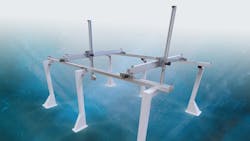
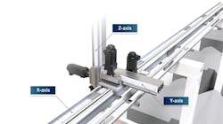
A wide variety of industries operate factories with large-format manufacturing lines, creating a need for long-travel motion axes and transfer robots. Some of these gantry and Cartesian robots can reliably traverse distances of 50 meters or more as they transfer materials and parts around aerospace, automotive, prefabricated construction and other large-scale factories.
A common design approach with long-travel linear robots is to construct them from belt-driven linear axes, which seemingly scale well to long distances. However, not all belt drives are created equal. Traditional belt drives, in which the motor remains stationary and drives the belt via a pinion, can limit the motion system’s performance due to belt sag and varying stiffness along the belt length—both problems that become more pronounced as travel lengths exceed 15 meters.
READ MORE: Optimizing Linear Motion Solutions Using Hybrid Automation Systems
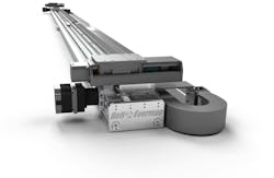
An alternative approach is to use an advanced belt-drive in which the motor is mounted to and moves with the belt drive’s carriage. A ServoBelt Linear (SBL) drive operates this way and very differently from a conventional single-belt drive. This moving-motor design has a number of performance advantages, which are magnified as travel lengths increase.
This article examines some of the drawbacks associated with conventional belt drives and show how moving motor designs can improve the performance of long-travel motion control systems.
The Problem with Belt Drives
Conventional belt drive actuators or stages have an obvious problem as they scale to long lengths. Because the belt is often unsupported, it causes the belt to sag or droop in the middle while the belt remains tight at both ends, imparting an asymmetrical, variable stiffness within the belt as the payload travels. Stiffness reaches near-symmetry when the payload is at the maximum or minimum distance away from the static motor that drives the belt.
The variable stiffness of a standard belt drive is a considerable challenge when aiming to accurately convert rotational motion to linear motion. Without accurate rotational-to-linear conversions, it is difficult to achieve accurate control and positioning. Engineers attempting to implement high-performance control models in their belt driven actuator will need to perform control-loop tuning in the belt’s least-stiff orientation as well as additional detuning—or invoke complicated gain scheduling schemes.
These control and positioning hurdles must be overcome in order to achieve a precise and accurate linear motion system, but it is often not worth the time, money and effort to develop the necessary control models. For these reasons belt drives are generally relegated to simple material-handling tasks.
The Benefits of Moving Motors
The commonly sought-after advantage of the conventional static motor approach is to limit the moving mass of the axis to only the payload. This may be a cost-effective solution in short-length, light-duty applications. While using static motors to drive a linear axis is an adequate design for less-demanding applications, performance falls short when travel lengths exceed the critical length of 15 meters.
At this length and beyond, the advantage of a reduced payload weight is more perception than reality. This traditional design isn’t just vulnerable to backlash, inertial forces and difficult-to-achieve precise positioning—it also incurs high costs when manufactured at long lengths.
READ MORE: Cut Time and Costs by Customizing Motion Control Systems with Standard Components
Properly designed moving motor drives deliver essential benefits to long-length motion axes, including maintaining driveline stiffness throughout the entire travel length, despite adding weight to the payload. This design also allows for multiple carriages to travel on the same axis, as well as both vertical and horizontal application. With this design flexibility, moving motors provide major throughput advantages by enabling multiple operations to be performed on the same axis—changing the game in long-travel motion systems.
While static motors are often implemented to lighten the payload, in long-length applications, they generally feature long recirculating belts that outweigh any light-weighting advantages. At the critical length of 15 meters and longer, the driveline belt is too heavy and actually hinders performance.
By comparison, moving motors boost an actuator’s efficiency by enabling designs with lighter belts, essentially removing mass from the entire drive and actuation system. It may seem counterintuitive to add weight to the payload with a shorter recirculating belt that is contained within the linear stage housing, but the efficiency gains are actually greater than initial expectations since long, heavy belts are no longer a driveline component.
A driveline needs to be as stiff as possible to achieve smooth and accurate linear motion. Many in-series elements—from the motor’s magnetic fields to payload weight—define driveline stiffness. Moving-motor designs keep the belt short, light and tight. And since the active portion of the belt is contained within the motor housing and not located adjacent to the motor, it maintains a constant, symmetrical driveline stiffness as the payload moves.
Symmetrical driveline stiffness also improves a moving motor’s positioning accuracy and enables linear motion system designs that feature a zero-backlash driveline. With a zero-backlash driveline, linear encoders can directly read the load position, facilitating closed servo-loop operation and other housekeeping functions such as sinusoidal motor commutation.
READ MORE: Linear Motion a Lifeline in Medicine
Keep in mind that to achieve a zero-backlash driveline without incurring torque ripple effects, it is necessary for the driveline to exhibit some degree of compliance and damping properties. Without a damped driveline, high-frequency disturbances will transmit into the rest of the structure. However, belts designed with stiff-yet-compliant materials can nearly eliminate backlash and deliver precise motion.
When Non-Standard Solutions Achieve Success
Moving motors are an effective design that outperform static motors in long-travel linear motion applications—and at a reduced cost. They provide excellent driveline stiffness, positional accuracy and energy efficiency while allowing multiple carriages to travel along the same axis. This design successfully stands up to motor inertial factors such as backlash, driveline stiffness and speed that inhibit long-travel motion axes.
This article was submitted by Michael Everman, founder and CTO of Bell-Everman.
The Pros and Cons of Standard Linear Motion Solutions
There are multiple design strategies to achieve linear motion, but adhering to conventional designs can limit the performance of a linear motion system.
While gear drives are commonly used, they often result in performance compromises regardless of type, size, material and other properties. Belt drives are also viable for linear motion systems, but conventional belt drives often face stiffness-related challenges.
When specifying a long-travel motion system, it is important to recognize the benefits and drawbacks of both gears and belts.
Gear Drives
Gear-driven systems often achieve accurate positioning due to their excellent driveline stiffness, but they introduce backlash or play—when gears are turning without moving the payload. Backlash prohibits direct encoder readings, which makes it a challenge to obtain precision in bi-directional repeatability.
However, backlash is often eliminated by removing any clearance between gear teeth. The lack of space between gear teeth with little to no compliance causes metal gears to generate a pronounced torque ripple effect, applying mechanical stress to other in-line components.
Nearly all modern manufactured gears are designed with involute teeth profiles as a means to eliminate backlash while delivering the smoothest possible conversion of rotary to linear motion. But no gears achieve 100% smoothness. The torque ripple effect is inherently present within gears, responsible for the noise, inefficiency and wearing of gear drives.
A traction drive is an alternative to the standard gear drive. Based on a gear type with practically “infinite teeth,” it attempts to eliminate torque ripple.
Traction Drives
Also known as capstan drives, traction drives minimize torque ripple effects in order to maximize smoothness and efficiency. However, they only achieve this performance improvement at the cost of individual tooth depth and strength, as well as reduced force capacity.
Traction drives may practically eliminate the torque ripple effect, but they also bring new issues like drive roller and bearing runout (the radial error about the central axis in a rotational mechanism). Special concern is also necessary to maintain traction on the rail; enough force must be applied to induce motion, but not so much as to cause slip.
While traction drives reduce backlash and improve efficiency, they lack force damping and economical payload capacity. A possible solution to these performance challenges is to design the traction drive with softer materials such as elastomers. But when an elastomer traction drive rests for extended periods of time, flats will form on the wheel’s surface that will negatively impact motion and positioning.
Rack and Pinion Drives
Rack and pinion drives are commonly used in Cartesian gantry designs, but their cost quickly balloons when manufactured or pieced together to long lengths. And because rack and pinion drives are designed with conventional gears, they are prone to backlash issues.
Designing the rack and pinion with spring-based anti-backlash creates an asymmetrical stiffness on either side of the payload, increasing the difficulty of achieving high-gain servo tuning.
Multi-Axis ServoBelt Linear
The ServoBelt Linear Advantage
Both short- and long-length linear motion applications can benefit from an innovative linear-actuator design, which outperforms conventional belt-drive designs. The ServoBelt Linear actuator, for example, differs from conventional single-belt drives by utilizing two mating sets of polyurethane, steel-reinforced gear teeth that perfectly mesh together. This actuator design is topologically similar to a rack and pinion, and visually similar to an “omega” belt drive.
This actuator design allows the driving belt to remain under constant tension around the pinion, minimizing belt stretch and uniforming driveline stiffness throughout the entire motion travel length. For further precision and accuracy, a ServoBelt Linear actuator’s belt mesh is preloaded on either side of the pinion—ensuring zero backlash as the carriage moves in either direction. Zero backlash allows the use of linear encoders, which allows performance only matchable by linear motors.
These actuators are ideal in high-performance applications because of their precision, repeatability, cost and speed. They are ideal for applications in semiconductor manufacturing, packaging, aerospace assembly and other high-performance, high-precision industries.


