READ MORE
What Determines the Stall Torque of Brushless DC Motors?
The Advantages of Slotless Motors over Standard BLDC Motors
Running Brushed DC Motors as Generators
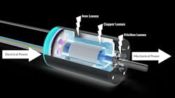
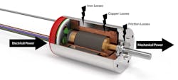
Brushless DC (BLDC) motors transform electrical power into mechanical power. However, there’s no such thing as a perfect motor; there are always losses in the transformation. The three main types of losses created during the conversion are friction losses, copper losses and iron losses.
Friction losses are caused by the ball and bush bearings, and they are function of the application’s use (speed, load and acceleration) and environment (temperature, dirt and other factors), plus the bearing’s intrinsic characteristics such as material, wear, lubricants and sealing.
Copper losses, also called joule losses, are created by the coil’s resistance. Torque is linearly proportional to the current, so the more torque a motor provides, the higher the copper losses. This follows the quadratic function shown here:
Copper Losses = R × I2
R is resistance and I is current.
Keep in mind that the resistance will increase as the motor heats up (according to the equation below). This will reduce the efficiency.
R = R0 × (1 + (𝑦 × ΔTemp))
R0 is the resistance value at ambient (usually listed in the datasheet), and 𝑦 is resistance factor of copper (0.004/°C).
Iron losses can be easily misunderstood but they have a substantial effect on motor performance. The losses depend greatly on the frequency of the variation of the magnetic flux into a material, so more losses are generated the faster a motor rotates.
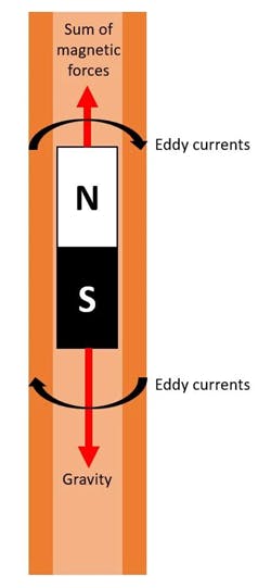
A small experiment can explain this phenomenon. When a magnet is thrown into a slightly ferromagnetic tube—like copper or aluminum—the speed of the falling magnet is much lower than what would be expected.
Why does this happen?
Lenz’s Law states that:
Induced EMF = −Δɸ/Δ𝑡
Δɸ is the rate of change in magnetic flux and Δ𝑡 is the corresponding change in time.
According to Lenz’s law, when the magnet falls through the tube, the changing magnetic field induces current that flows in a direction that opposes the change in the magnetic field that produced it, thereby reducing the magnet’s speed.
Iron losses are generated by two phenomena: eddy currents and hysteresis.
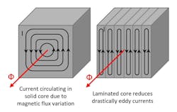
Eddy currents. Faraday’s law states that a magnetic field interacting with a conductor induces a current through it. And, since the material has a specific electrical resistance, it creates some iron losses (R × I2). So eddy current are calculated using:
Eddy current losses = R × I2 ≅ C × B2 × 𝑓2 × 𝑡2 × V
Where: C is a constant depending on the motor design and materials; B is the magnetic field into the materials (T); 𝑓 is the frequency of magnetic reversal per second (Hz); 𝑡 is the material’s thickness (m); and V is the volume of the conductor (m3)
The previous formula shows the parameters that play a large role in creating eddy current losses above. Not surprisingly, the frequency of magnetic field reversal has a substantial influence, as does the motor’s speed. The intensity of the magnetic field and even the thickness of the material also play important roles.
An effective way to reduce the impact of the material’s thickness is by laminating the core material (as shown in the image above). This creates a shorter path for the current to travel through, thereby splitting it into several small currents. Because losses are created with the squared value of the current, this approach is highly effective. So, to avoid current flowing between two laminations, insulate the laminations from each other with a coating.
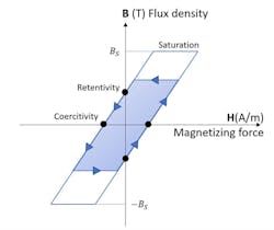
Hysteresis. When the magnetic flux is reversed into a ferromagnetic material, energy is lost as the material magnetizes and demagnetizes. To remove the remaining flux density, an opposite magnetic flux should pass the point of coercivity (as shown below).
These losses depend primarily on the magnetic induction in the circuit, but also on material properties such as permeability, volume and the flux variation’s frequency. That’s why it is important to select the right material for the right speed.
The Steinmetz equation can be used to calculate hysteresis losses and understand the influence of each parameter. It states:
Hysteresis losses = k × V × 𝑓 × B × n
Where k is a constant of the material; V is the volume of the magnetic circuit (m3); 𝑓 is the magnetic field’s frequency; B is the maximum induction in the magnetic circuit (T) and n is a coefficient (between 1.6 and 2) that depends on the material
Getting the Right Motor
An BLDC motor’s various limit its maximum power, since it would burn if it exceeded a specific temperature depending on the motor design. This makes it critical to select the right motor based on the specific torque-speed working point.
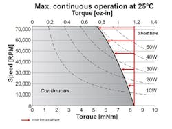
Copper losses are mainly created when the motor is generating torque, and iron losses usually occur at high speeds. Consequently, the figure below shows that for a given motor, the maximum possible continuous torque decreases when speed increases.
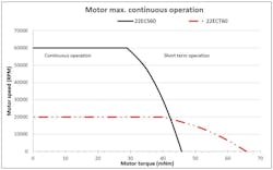
Changing the number of poles of a magnet can have a major influence on motor performance. Typically, long motors have two-pole magnets and can run at high speeds. Although this can increase the motor’s maximum torque, it also increases iron losses and thus reduces the maximum continuous speed.
Iron losses depend highly on the frequency of variation of magnetic flux for a similar speed, so increasing the number of poles increases the number of variations for one motor turn. For eddy current losses, this happens with the square of the increased frequency and can quickly reduce a motor’s efficiency.
When selecting an electric motor, it is critical that engineers consider the different losses. Because the motor’s limits are thermal, iron losses play a role in the motor’s efficiency, especially at high speeds or in multipolar, high-torque designs. Optimizing the ratio between copper and iron losses will save energy and improve motor designs.
Samuel Klein is an application engineer at Portescap.
