Over the last decade several design methodologies and manufacturing processes have appeared that, when employed, lead to automatic DFMA results.
Here’s look at several of them that have been shown to help designers and engineers achieve several DFMA goals—the primary one being reduced part count, which saves money and simplifies assembly.
Electronic Packaging Assembly Concept
In the 1990s, steadily decreasing market prices and shorter life cycles crippled Hewlett-Packard’s workstation business. The company decided it suddenly needed faster production processes.
Hewlett-Packard’s workstation design team, needing to reduce the cost and time it took to building its workstation, had an epiphany. As one of the designers recalls, “The team could not get out of their minds the idea of fixing parts so that they are enclosed and held by their by geometrical forms. The idea is similar to children’s games that require players to put differently shaped blocks into matching hollows.”
For the workstation, the blocks would be the workstation’s electrical and mechanical components, while the hollows would be spaces inside the workstation’s enclosure. The critical step turned out to be finding a suitable material in which to carve out spaces for components inside the enclosure. The material would need to:
- Be pliable and bouncy.
- Be 100% recyclable.
- Be nonconductive.
- Hold tolerances.
- Attach components to substrates without fasteners.
- Resist heat, chemicals and moisture. The material that seemed most suitable was expanded polypropylene (EPP).
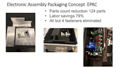
Creating the prototype with EPP foam required two days to fabricate the parts and assemble the workstation. With a few minor alterations required for air flow, the workstation not only ran, but passed all environmental tests as well. Compared to the traditional workstation, the Electronic Packaging Assembly Concept (E-PAC) workstation needed:
- 70% fewer housing parts.
- 95% fewer screw joints.
- 50% less assembly time.
- 90% less disassembly time.
- 30% less transport packaging.
- 50% less time and cost in developing the housing.
Moreover, the E-PAC workstation included these additional benefits:
- Fewer chassis parts.
- A one-step process to make molded parts.
- Simple, fast, cost-effective assembly.
- A lighter final product.
- Shock and vibration protection.
- Cooling from air channels in the foam.
- 100% recyclable materials.
- Fewer tolerance issues due to material flexibility.
3D Molded Interconnect Devices
3D Molded Interconnect Devices (3D MID) are made using laser direct sintering (LDS). LDS was invented at the University of Applied Sciences in Lemgo, Germany between 1997-2001, and the technology patents were eventually licensed to LPKF Laser & Electronics AG.
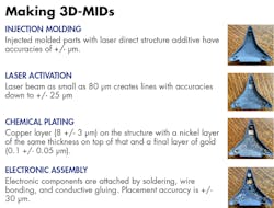
Interconnects start out as an injection molded polymer part with an additive (usually copper) in the polymer. The top layer of plastic is removed using LDS, which exposes and forms a micro-rough copper surface. The part is cleaned and then dipped in a copper bath to add more copper to the interconnect. Next, a thin layer of nickel—and usually a thin layer of gold—are deposited on the copper. Other coatings can also be added, including Sn, Ag, Pd/Au and OSP. Finally, electronic components are added. If the polymer has a high-enough heat resistance, these components can be connected using a standard solder reflow process.
Combining electrical and mechanical/material features yields:
- Lowers part count.
- Simpler assembly.
- Smaller, lighter and more reliable interconnects.
- More design flexibility due to use of three dimensions and polymer’s mechanical properties.
Electronic Magnetic Assembly Bonding
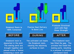
Electronics Magnetic Assembly Bonding (Emabond) applies 13.56-MHz electromagnetic radiation to a proprietary polymer which has iron or stainless-steel particles added to it to create permanent polymer-to-polymer bonds or welds.
The polymer is available in a wide range of formulations to match specific applications. It is available in several forms, including sheets, die-cut stamped gaskets, slit tapes, injection molded rings, 3D printed shapes and co-extrusions.
The main advantage of this process is it creates reliable welds regardless of the type of plastic and is compatible with almost any type of material.
Emabonding can be used to:
- Create hermetic seals.
- Join dissimilar and highly filled materials.
- Replace conventional adhesives to join parts.
- Treat surfaces before welding or bonding.
- Weld or join several bond lines.
- Create strong joints, including those that use gaskets.
- Prevent frequent or costly joint failures.
Hydroforming
Hydroforming is based on a 1950s-era patent for hydramolding which was developed at the Schieble Co. It was originally used to make kitchen spouts because in addition to strengthening the metal it made less “grainy” parts, which made it easier to give them a pleasing metal finish.
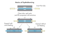
Hydroforming is a cost-effective fabricating and forming process that shapes metals such as steel, stainless steel, copper, aluminum and brass. It uses a special type of die molding and highly pressurized fluid to form the metal.
Hydroforming can be either sheet hydroforming or tube hydroforming. In sheet hydroforming, high pressure water drives a blank sheet into the die on one side of the sheet, forming the desired shape.
Tube hydroforming is the expansion of metal tubes into a shape using two die halves which contain the raw tube. This type of hydroforming replaces the older process of stamping two halves and welding them together. Tube hydroforming makes parts more efficiently by eliminating welding and can make complex shapes and contours.
Hydroformed parts have several advantages for manufacturers, including seamless bonds, stronger parts and high-quality surfaces for finishing purposes. And compared to traditional metal stamped and welded parts, hydroformed parts are lightweight, have a lower cost per unit and feature higher stiffness-to-weight ratios.
From a DFMA perspective, hydroforming:
- Creates complex, 3D geometries and cross-sectional and perimeter modification in just a few steps.
- Lowers costs through material reduction by using thin-walled tubes, and end up with parts that have the same or higher static strength as cast or bent parts.
- Replaces several steps such as joining, soldering, welding and milling with a single hydroformed component.
- Consistently turns out precise and accurate parts.
- Extensive repeat accuracy of geometries.
- Allows use of several materials including aluminum, stainless steel, brass, copper and nickel-based alloys.
- Lets companies standardize components across entire product range.
3D Printing
In 1981, Hideo Kodama of Nagoya Municipal Industrial Research Institute published his account of a rapid-prototyping system using photopolymers. In it, solid, printed models are built in layers, each corresponding to a cross-sectional slice in the model.
Three years later, Charles Hull invented stereolithography. It lets designers create 3D models using digital data that can then be used to create tangible objects. The key to stereolithography is an acrylic-based material known as photopolymer, a liquid that solidifies into solid plastic when exposed to a UV laser. By controlling the position and strength of the laser, 3D printers can build parts one layer at a time. This lets designers prototype and test designs without a large upfront investment in manufacturing equipment.
By 1992, 3D Systems developed the first stereolithographic apparatus (SLA), which made it possible to fabricate complex parts, layer by layer, in a fraction of time it had previously taken. That same year, startup DTM made the first selective laser sintering (SLS) machine. It shoots a laser at a powder instead of a liquid.
Since then, 3D printing has taken off. Several materials can be printed, including most polymers, composites, metals and even human biological tissue. Everyday new 3D printing applications are devised, and 3D printing methods continue to evolve.
Friction Stir Welding
Friction stir welding (FSW) was invented by Wayne Thomas and colleagues at The Welding Institute in Cambridge, England, 1991.
The process of friction stir welding spins a mechanical tool along the line between disconnected two pieces of aluminum. The part is shaped to create enough friction to melt the aluminum along the line between the parts as it spins. It is also shaped to sweep melted material from in front of the tool to the back where it solidifies into a strong, reliable weld. Friction stir welding works on parts thicker than 75 mm, as well as those as thin as down to 300μm.
Friction stir welding advantages include:
- Low distortion and shrinkage, even in long welds.
- Maintenance of excellent mechanical properties and, in many cases, improvement of the microstructure and strength.
- No arc or fumes.
- No porosity in weld zone.
- No splatter during welding.
- Welds three dimensionally.
- Energy efficient.
- One tool can typically be used for up to 1,000 m of weld length in 6XXX series aluminum alloys.
- No filler wire or gas shielding needed to weld aluminum.
- Works despite imperfect weld preparations and joint match up. Parts can even have thin oxide layers.
- No grinding, brushing or pickling needed in mass production.
All of these design methodologies and manufacturing techniques when implemented yield DFMA-like results. They simplify products and manufacturing processes; eliminate parts; save assembly labor; and overall reduce costs and improve quality.
For More Information
- EPAC: Contact Tim Schwegler of Particular Particle.
- 3D MID: Contact Will Slade of Brayden Technical Agency.
- Emabond: Contact Steve Chookazian of Emabond Solutions, LLC.
- Friction stir welding: Contact TES Canada Inc.
David Meeker is a consultant at his firm Neoteric Product Development.
