DFMA Redesign Leads to Reusable Parts That Withstand the Heat
Engineers at Nieka Systems in Canada design x-ray equipment that determines the compositional makeup of ore and cement samples. They also design and manufacture the equipment needed to mix and dissolve samples in molten borate at temperatures over 1,000°C to make the material samples compatible with the analysis process.
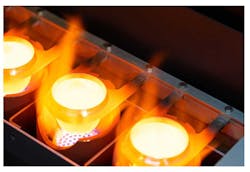
The materials and borate are mixed and heated in platinum crucibles which are suspended by thin metal clips. Nieka System’s founder, Louis Croisetière, wanted to redesign the clips using DFMA principles to lower costs.
There were several goals for the clip’s redesign. The new clip would need to:
- Hold the crucible in place throughout the mixing and pouring operations.
- Minimize heat transfer from the crucible to the rest of the machine.
- Keep its strength and durability despite high temperatures.
- Have lower manufacturing costs.
- Make lead times shorter and more predictable.
Deciding the clips’ material was relatively simple. The high temperatures and rapid temperature changes made the nickel-based superalloy Inconel 625 a natural fit. Choosing that exotic metal introduced several manufacturing complications.
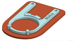
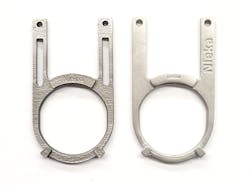
At first, Nieka wanted to use CNC machining to prototype and manufacturing the clips. The company designed a clip that met the mechanical requirements and had a slot in each of the clip’s legs to minimize heat transfer. A design evaluation concluded this would be difficult to manufacture using CNC machining and lead to steep costs, long lead times and machine shops declining to take on the job.
CNC machining also meant the clip had to be cut from a much larger volume of Inconel 625 stock, so much of it was lost to waste. Inconel 625 also can quickly wear down slotting tools required to cut the overhangs that hold the crucible. Keeping the clip in position while it was machined was also a challenge: It took several set-ups, and the clip tended to bend under the forces from the vice holding it.
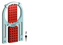
To lower the cost for complex parts made in low-volume production, Nieka turned to direct metal laser sintering (DMLS) and an outside vendor. Although the original CNC clip design was already DMLS-compatible, there were other complications. The clip was 3D printed upright to simplify removing it from the build platform. In this upright orientation, support structures were needed to anchor the part during fabrication. Although an outside DMLS vendor agreed to remove these structures, it added lead time and occasionally left rough surfaces that required post-processing.
More significantly, Nieka did not have enough orders to fill an entire build platform. To keep costs down, the vendor delayed making the clips until it had enough orders to run a full build. This led to inconsistent and unpredictable lead times varying from 14 to 40 days, which hindered R&D and production planning. These supply chain constraints led Nieka to seek an in-house metal AM technology, leading to a new design for the crucible clip.
A Flexible Manufacturing Solution
Nieka needed a more flexible manufacturing method that could be done in-house. The company eventually chose metal fused filament fabrication (FFF) on a Metal X printer from Markforged. Of course, this also called for a redesign of the clip, as the FFF process involves 3D printing using a polymer and wax filament which contains metal powder, then removing the wax and polymer and sintering the metal powder into a metal clip.
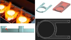
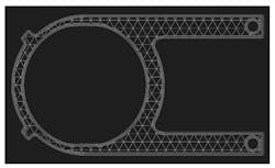
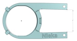
FFF let Nieka engineers create complex clip geometries to meet their design goals. They also used Eiger slicing software from Markforged to create a hollow triangular infill in the clip’s CAD model. This eliminated the need for the cooling slot and meant that less heat-transmitting Inconel was needed to make each clip. The new design prevented much of the heat from escaping the crucible, and the new leg was stiffer than the DMLS version.
Eiger slicing also creates a “raft” underneath printed parts to improve geometric stability during sintering. This normally has minimal impact on process costs, but the crucible clips are so small that printing the raft doubled the print time and material cost. Nieka’s engineers chose to forgo the raft, doubling daily production capacity but also causing the legs of the clip to go slightly out-of-parallel during sintering. This was a classic engineering trade-off—a small reduction in dimensional accuracy increased production capability.
Fortunately, the resulting problem of legs that were out of parallel also had a simple fix. The clip’s legs always bent outwards by a repeatable angle during sintering, so they were redesigned to angle inwards by the same amount and they would be straight and parallel after sintering.
Subtle modifications created efficiency improvements in processing FFF parts after sintering. A small chamfer added to the lip that retains the crucible flange reduced the amount of support material used in that region. This created a bigger gap between the support material and the part and made it easier to remove any remaining support material.
Redesigning the crucible clip for the Markforged FFF printer lets Nieka Systems consistently deliver lead times and cost savings at least an order of magnitude better than CNC machining or DMLS could, while improving the clip’s performance.
It also has changed the way the Nieka designs its products. “Some of our new designs are based on the fact we can print parts, so it’s changed the way we work,” says Croisetière. “It’s reduced our assembly time and we have none of the design limitations of traditional methods.”
