Getting the Right Stepper or Servo Motor for Electric Actuators
As the shift to automation continues to gain momentum in the industrial sector, servo motors and stepper motors with electric actuators become ever more important. When selecting a motor for an application, it is the functions that are important, not necessarily the construction.
Here’s a look at servo and stepper motors’ characteristics as they relate to linear motion. (Brushless DC motors will be considered servo motors for this article.)
Torque vs. Speed
Servos have a constant torque over their total usable range of speeds. So, if a servo motor has 1.2 Nm of torque at 10 rpm, then it also has 1.2 Nm of torque at 3,000 rpm.
Steppers on the other hand, have their maximum torque at low or zero speed and it falls off quickly at the much lower speed of a servo. If a stepper has 3.4 Nm of torque at 1 rpm, it is not unusual to see a drop to 0.2 Nm at 1,200 rpm.
Engineers should look at each motor’s torque curves to select the proper size motor for an application.
Servos go faster than steppers no matter what the torque is. In some applications, this lets a gearbox be used with a servo to increase the torque for the application. The gearbox multiplies the torque by its ratio and the motor rpm will go up by the same ratio. Engineers should be careful not to exceed the motor’s maximum rpm.
For example, a motor with a torque of 2.3 N m at 500 rpm when used with a 3:1 gearbox will have a 6.9 N m output, but the motor’s rpm will climb to 1,500 rpm to drive the gearbox. Steppers’ higher torque and lower speed curve generally mean they will not use a gearbox.
Feedback
Steppers are generally open loop. Position is determined by the number of steps or pulses given to the motor for it to rotate. The total number of steps equals the motor shaft’s amount of rotation or rotations. If a pulse is missed or the motor cannot move after the pulse because it lacks the power to rotate the shaft, then a position error is introduced but the motor/drive does not know it.
This can be a problem in some applications and is taken care of by re-zeroing the system back to home. Also, an external sensor or encoder (rotary device mounted to motor that outputs shaft position) can be used.
Servos, on the other hand, are inherently closed loop and use an encoder. Using an encoder lets them constantly monitor their position, current and speed versus what the motor has been told to do. If position falls behind, the controller can increase parameters to catch up. As such, the motor is always under control. If it cannot catch up, the controller knows it and will generate an error alert to make the problem known.
Load Holding
Actuators often need to hold position at zero speed. How this is done by servos and steppers differs and often not considered by designers.
A stepper, as noted above, has maximum power at zero speed. It will hold this position with full torque until another pulse is received telling it to move. It is open loop with no feedback. As long as the holding torque is enough, generally sized for 50% more than needed, this can be ideal for holding a load at a standstill.
If the stepper is not sized correctly and the load changes, the motor can stall, and pulses are missed. There is no feedback for this, so there ends up being an error in positional accuracy. However, steppers are the most economical solution, and in low-speed applications they deliver more torque than a servo.
A servo does not use the same procedure. Instead, it monitors the encoder to stay at a zero-speed position. Usually, a programmed plus and minus window is used to define In Position. This means the motor is told to move back to a position when the controller sees a difference that puts it outside the In Position window. This movement must be planned for in critical applications by using motor resolution that is more than the application needs, so that position hunting or dither is not seen by the actuator rod or carriage.
Servos can usually generate up to three times their constant torque for a short period. This gives them reserve power needed to compensate for load changes without being greatly oversized. The servo monitors the encoder position and can increase speed or current to get back in position when it sees a difference.
Accuracy and Repeatability
Both motors are generally accurate and repeatable enough for most industrial linear motion applications, mainly because of a gear reduction. This can be the ball screw’s pitch or a gearbox giving advantage of more position counts on a measured linear position. Remember, these actuator applications typically use belt or screw drives. A 1,024-count encoder used with a 5-mm pitch ball screw has a control resolution of 0.005 mm per count (5 mm/1024 = 0.005 mm/ct.). For general industrial application, this is normally very good and can easily be increased if needed.
These resolutions need to be calculated for each application, but any required positional resolution can be done for most industrial applications.
Motor Selection
Here are some general guidelines for choosing between steppers and servos:
- If low cost is needed, a stepper is a good choice.
- If loads are unpredictable and create extra torque requirements, a servo is a good choice.
- If complete reliability even with power loss is needed, a servo should be chosen.
- If it’s a low speed or low torque application, a stepper should be used.
Engineers may need to go through the specific characteristics of the motors and look at the pros and cons of each for applications they are working on.
However, if there is no clear choice on motor type because features of both steppers and servos are needed, perhaps a stepper with servo control is a good option.
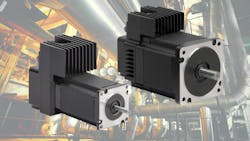
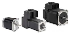
There is also a new type of motor being used: the hybrid stepper. The ServoStep motor offers the benefits of steppers and servos by having some characteristics of both. They provide a closed loop on the stepper motor to get some of the advantages of the servo control.
Stepper and servo motors offer a wide array of features that can benefit specific applications. The key is understanding what the application requires and selecting a motor that best meets application requirements and complies with engineering specifications. While this article offers the basic information needed to choose the motor type for an electric actuator application, there are also other elements needed to complete the system. These include a drive/controller, smart controller, serial or discrete control, and proper sizing for the application.
Automation engineers are a good resource when designing complete systems and they can offer more details specific to an application.
Ed Hess is a senior automation engineer at Flow Products Inc.

