Smart Conveyor Control Using VFDs and Sensors
At a Glance:
- What does a simple cascaded conveyor system look like?
- How to integrate a conveyor system using only the digital capabilities of modern variable frequency drives (VFDs).
- Simplifying the automation circle for a conveyor system using sensors and VFDs only.
From transporting trays of food across your everyday cafeteria line to feeding coal into the world’s supercritical thermal power plants, nearly every industry relies on cascaded conveyors. In the most complex environments, these systems work harmoniously in multiple cascaded systems to deliver material from point A to point B in a coordinated manner. In these instances, however, if one conveyor belt in the cascaded conveyors stops, the feeding conveyors automatically stop in order to avoid material pileups.
In these cascaded systems, the safety mechanism to turn off the drive powering the conveyors is similar to an emergency stop. This feature is very important when used in combination with preventative maintenance measures in the plant or process where these conveyors run continuously (24/7). The control and automation systems could range from a simple material handling system to a very complicated system designed to cater to multiple combinations of the conveyors.
For large material handling systems like those in thermal power plants, where the human machine interface is required to either manually or automatically select the paths, a distributed control system or a programmable logic control (PLC) typically needs to be used.
However, in simple systems such as the conveyor system in a stone crusher quarry or a large cafeteria, only digital VFDs and sensors can be wired and programed to conduct the cascaded operation, as opposed to using a PLC. This approach offers benefits including lower engineering, commissioning and troubleshooting costs to implement a fully integrated cascaded conveyor system.
What a Simple Cascaded Conveyor System Looks Like
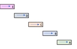
A simple cascaded conveyor system will look like the one shown in the figure below. Certainly, along with the conveyors, there would be pull cords, zero speed switches, proximity sensors, photo sensors and vibration sensors. Diverter gates or flaps are also part of the conveyor system to divert the material on the conveyor to deliver it at the correct delivery point. An AC induction motor that is being controlled by a VFD is running each conveyor A through E.
In the non-digital age, all sensors were wired to a control contactor logic. Today’s digital VFDs allow direct wiring of sensors to the VFDs, and in some more advanced systems these sensors can be wired directly to a PLC.
How a Typical Conveyor System Operates
The most important aspect of any process is safety. All conveyor system safety sensors (such as pull cords or emergency stop buttons) should be verified for system readiness. Then, the diverter gates at the entry and exit of the conveyor are set in the direction to set the conveying path for the system.
Depending on the number of installed sensors and the overall fidelity of the conveyor system, the start/stop command is given manually to each conveyor. Otherwise, the system can be given a system level start/stop command and then the sensors will start and stop the individual conveyors in the system.
After the cascaded conveyor system receives the “start” command, the conveyor that starts first will be the last to stop when the system stop command is issued. A visual of this logic can be portrayed using Fig. 1 and is outlined in the steps below:
When the start command is issued, the conveyor system will follow the following start sequence:
- The conveyor A is the first one to start;
- Then conveyor B will start running after conveyor A has started running;
- Then conveyor C will start running after conveyor B has started running;
- Then conveyor D will start running after conveyor C has started running;
- Then conveyor E is the last one to start.
When the stop command is issued, the conveyor system will follow the following stop sequence:
- The first conveyor to stop is conveyor E;
- Then conveyor D will stop after conveyor E has stopped;
- Then conveyor C will stop after conveyor D has stopped;
- Then conveyor B will stop after conveyor C has stopped;
- Then conveyor A will be the last one to stop.
This same logic applies when any of the conveyor sensors in the cascaded path communicates an issue such as a motor fault. Therefore, if conveyor C trips on a fault, conveyors D and E will have to be stopped so that material does not pile up on stopped conveyor C. In a more complex system, users can choose to divert the material to a different path rather than stopping conveyors D and E.
As demonstrated in the model above, sensor integrity is critical for maintaining the effectiveness of cascaded conveyor systems. The most typical type of sensor found on conveyor belts is a zero-speed switch. This solution provides true feedback regarding the status of the conveyor belt motion.
For example, these sensors should be effective in situations where an AC induction motor could be moving because the VFD is putting out voltage to the motor, but the conveyor belt/chain could be stopped because it is broken. In the figure above, if the zero-speed switch on conveyor C triggers, the motors on conveyors C, D and E should be stopped to prevent material pileup.
The implementation goal of zero-speed switch sensing controls is to ensure accurate sensing after the conveyor drive has started running at a certain frequency, but not until the conveyor drive has started moving. This is important, because if a sensor indicates zero-speed before the conveyor starts running, the conveyor would never start.
Before the digitalization of today’s VFDs, PLCs were a must for implementing digital control for a simple cascaded conveyor system. Before PLCs, hard-wired relay control was used. Following the advancement offered by VFD digital controls, most of the control functions required for a simple conveyor system can be achieved by integrating the sensors to the VFD and the interconnecting wiring between the VFDs.
This VFD-based approach can help improve return on investment, as it is able to achieve the same performance without the additional cost of integrating the VFDs and sensors and programing PLCs.
Integrating a Conveyor System Using Digital VFDs
To demonstrate how to integrate a conveyor system using digital VFDs, let’s again take a look at the system in the figure above.
Start command. Five VFDs, one for each conveyor motor shown, is hardwired connected to each other on the control board of the VFD. Run feedback from conveyor A is wired to conveyor B, conveyor B is wired to conveyor C, Conveyor C is wired to conveyor D, and conveyor D is wired to conveyor E. The system start command is issued to conveyor A only and the run feedback signal wired between the conveyors start conveyor B; B starts C; C starts D; and D starts E. This is how the VFD controls start all five conveyors.
Conveying speed reference control. The main system speed reference input is only fed to conveyor A’s VFD. Conveyors A, B, C and D’s VFDs then feed the speed control signal upstream in cascaded conveyors—that is, A → B → C → D → E. Changing the speed reference to conveyor A subsequently changes the speed of the conveyors upstream feeding material into conveyor A.
Stop/fault command. Five VFDs, one for each conveyor motor shown above, are hardwired connected to each other on the control board of the VFD. The stop from conveyor E is wired to conveyor D, conveyor D is wired to conveyor C, conveyor C is wired to conveyor B, conveyor B is wired to conveyor A. The stop command is issued to conveyor E and the stop feedback to conveyor D stops conveyor D, D stops C, C stop feedback stops B, B stops A. This is how the VFD controls stops all five conveyors. Similar to a “stop” command, the fault on a conveyor follows the same stopping sequence, again achieved by VFD interconnection wiring.
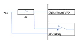
Sensor interface. As the fidelity of the system increases, users add more and more sensors to the conveyor system. Let us start with the zero-speed switch. The switch from each conveyor is wired to its specific drive external fault. That is, if the switch triggers, it will fault the VFD it is wired to and the subsequent VFDs in the chain will stop due to stop logic. The simple way to bypass the zero-speed switch when the drive is not running is to use VFD relay to supervise the drive frequency to be above where the conveyor is already moving.
Once the supervising relay opens above the preset speed frequency setpoint, it starts to monitor the zero-speed input on the same channel where the supervision relay was connected for initial bypass of the zero-speed sensing. Again, simple control is achieved by using the VFD digital control without a PLC.
The pull cord of the conveyors can be wired in series to the STO of the drives. It’s the safest mode to put an E-stop to the VFDs running motors. All of this is being achieved by VFDs only.
Incorporating Other Control Interlocks
Other interlocks, such as proximity sensors, can be connected to the VFDs for a more intelligent start and stop of the conveyors by sensing the material on belt. Instead of running the conveyors continuously and consuming power, the proximity sensor or the current sensor of the drive will sense the load travelling on the belt, and presence of a load sensed by the VFD will trigger a start command to the next VFD conveyor in the path.
Take the example of the system shown in the top figure: The smart sensing would be the sensor or the VFD algorithm sensing the load on conveyor E. As soon as the load on conveyor E increases above a preset level, the start command to conveyor D is given by VFD E, and so forth, until the last conveyor in the path starts. Similar logic applies to stopping of the conveyors. If the load falls below the threshold, there is an indication that the load is not being transported, so the VFD in the cascade path can be stopped automatically to save power.
Maintenance management. Sensors with vibration monitoring capabilities can be wired directly to the VFD to generate warning and fault the system to prevent damage. Sending the status of equipment health such as temperature, load or speed to the user using an IoT-based phone app, without the need for a full-blown automation system, eliminates the need of a high-fidelity HMI or SCADA.
As summarized above, the single start/stop command to the sensor-based conveyor system helps implement an intelligent conveying system. All of the faults and the trips are interlocked in the cascaded conveyor system to prevent pileup of the material due to tripping of one conveyor in the path. At the same time, the VFDs are continuously monitoring the load current advising the user on whether to continuously run the conveyor, without wasting the power or shutting it down. As all VFDs are digital and enabled for the Internet of Things (IoT), all data is constantly being shared with the stakeholders who are managing the production and the commercial side of the business.
To draw an analogy, the IoT system helps maintenance and commercial teams run analytics in the same way QuickBooks serves the finance teams. This IoT-driven data analytics feature can help users optimize their processes by feeding digital data directly from sensors directly into a portal that is remotely viewable nearly anywhere.
In summary, the smart digital VFDs of today can very easily do the job of a small PLC while supporting IoT connection that allows users to monitor conveying systems remotely. This capability not only improves return on equipment and labor investments, but can also enhance overall business intelligence in terms of production, maintenance and safety management by providing the accurate, actionable data needed to improve processes.
Ranbir (Ron) Ghotra, PMP, is a product line application engineer at Eaton. He has 20 years of global experience in designing, engineering, commissioning and managing control and automation projects. He also has effective problem-solving skills in a wide variety of industries, from residential to aerospace. Ron is certified as a Project Management Professional (PMP); he has a Bachelor of Science degree in electrical engineering from NIT Rourkela, India and a Master of Business Administration from Katz Business School at the University of Pittsburgh.


