Unique Piezo Motion Devices Solve Design Challenges
Piezoelectricity—the characteristic of certain solid materials whereby electric charge accumulates internally and is released when the material is stressed—was discovered by Jaques and Pierre Curie in 1880. The reverse effect, whereby piezo materials will exhibit a deformation resulting from an applied charge, was deduced by Gabriel Lippman in 1881 and subsequently demonstrated by the Curies.
The first significant application for the technology was for sonar, developed in 1917. Piezoelectric devices are now widely used in sensors and small stroke actuators for diverse applications.
The first effective motors using the reverse piezoelectric effect were created in the mid-1960s at the Kiev Polytechnic Institute. The technology has continued to evolve, and today a range of linear and rotary motion devices are available offering precise motion control down to nanometer precision. However, they are typically high-cost devices and are primarily used in specific premium market applications such as optics, semiconductor and photonics.
Leveraging continued research evolving the founding work at the Kiev Polytechnic Institute, new methods for configuring and controlling Piezoceramic materials, along with novel techniques to establish motion devices, have been identified. These developments have led to a portfolio of patents that have in turn enabled the design of a range of linear and rotary motion devices with a number of useful technical benefits. These can be used by the medical device and instrument designer and be comparable in cost to typical good-quality dc and stepper motor solutions.
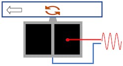
These motor designs use a patented configuration of a single monolithic piezoceramic drive element and a novel excitation method, which only requires one connection to simultaneously excite the piezoceramic to oscillate along and perpendicular to its axis. A high-frequency ac signal is applied to achieve resonance in the piezoceramic. The simultaneous excitation results in an elliptical motion being established on a drive tooth on the side of the element. A short pulse of around 30 microseconds results in the piezoceramic being excited into resonance and undertaking a single elliptical rotation at the drive tooth tip.
The revolving drive tooth can be applied to a linear or rotating element to create motion. The technology uses simple electronics and, depending upon the specifications, the applied voltage to the piezoceramic resonator is between 50 V and 80 V, which is lower than typical existing piezomotors.
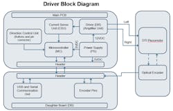
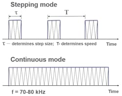
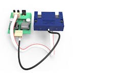
The motor is controlled with a simple piezomotor driver. Driver boards have a 5 V or 12 V supply, a three-wire connection to the motor and a three-pin connection for control. One control pin is ground and the other two establish motor movement in each direction when a transistor-transistor logic (TTL) high signal is applied. A continuous high will lead to the motor running in continuous mode in the direction selected. The motor motion can be controlled in open loop with pulse width modulation of the voltage applied to the control pins.
The motors can achieve very precise position control. A single incremental step on linear motors is under 50 nanometers. The rotary motors achieve rotary increments down to 10 microradians, which is more than 600,000 steps per revolution. For precise positioning, such as in optics and laser assemblies for mirror and lens control, this avoids the complexity and expense of gearing systems.
Piezomotors require no power when stationary and maintain full blocking force and torque in this condition. At one revolution per minute a rotary motor requires less than 0.1 Watts and linear motors only need 0.06 Watts to drive at 1mm/second. This can lead to low overall power demand and is especially applicable in portable instrument applications with a battery supply; it can also be beneficial in reducing heat generation inside equipment. For the same power as a comparable sized stepper motor the piezomotor has a stall torque up to 10x greater for the same power rating.
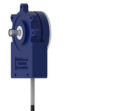
Designed with housings made from high-performance engineering polymers and containing no magnets, copper coils or iron laminations, these piezomotors are also lightweight, which is a further benefit for designers of portable and handheld devices.
The monolithic piezoceramic resonators are hard materials, and the resonator drive tip pushes against surfaces with specific controlled characteristics to achieve optimized motion transfer and long life. Testing has yielded in excess of 15 million full cycles on linear motors still maintaining performance within specification, which equates to 450 kilometers of linear travel. Rotary motors are on test and operational at over 40 million revolutions.
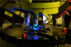
Piezomotors have very fast response times. From the applied signal they commence motion within 30 to 50 microseconds. The applied voltage leads to a rapid reaction in the piezoceramic, unlike electromagnetic motors which must generate a magnetic field and an applied force before motion can commence. This benefit has application in the automation of microscopy where up to several thousand high resolution images of a slide need to be taken to be processed and built into a single image—for example, in pathology imaging. Fast response times enable much-reduced overall processing time leading to faster throughput.
With the direct drive characteristics of the technology and the design philosophy, OEM versions of piezomotors can be made to optimize motion assemblies. This can give the designer the opportunity to greatly simplify the motion control system drivetrain and avoid rotary to linear translations and gearing.
Piezomotors can be designed with non-magnetic or low permeability materials, which make them suitable for use in MRI field applications. Application examples include motion control for medical surgical robots, precise pump control for infusion pumps and valve control for use in ventilators. A microdosing pump has been developed which can deliver media in doses as small as 1.6 nanoliters.
DTI piezomotors can be operated in open-loop mode with commands sent from a controller. Using pulse-width modulation, the size of each step is determined by the pulse duration, and the speed of travel is determined by the pulse repetition rate.
The minimum pulse duration is approximately 30 µs (microseconds). The maximum repetition rate (F), measured in Hertz, for a selected pulse duration (T), measured in seconds, is determined by the formula F = 1/T. The range of speed variation in PWM mode can be up to 6 orders of magnitude.
Motors are also available with fitted encoders to enable closed-loop control. A windows PC control software with a range of control commands is available to create motion profiles to drive the piezomotors.
Additionally, a Python API and a serial command set are available, which can be sent to the driver board via RS232 interface. In this way motor control can be established in any customer control platform for devices and instruments.
With closed-loop control there are different algorithms to optimize motor speed and position control, leading to quiet and accurate motor motion and positioning.
- Continuous-frequency algorithm – Medium to high speeds of 2 rpm to 100 rpm are regulated by varying the excitation frequency along the resonance characteristic of the piezomotor within its medium-frequency region during medium- to high-speed motion.
- Hysteresis algorithm – Low speeds of 1 rpm to 2 rpm are regulated by varying the excitation frequency along the resonance characteristic of the piezo motor within its high-frequency region during lower-speed motion.
- Modulation algorithm – Slow speeds of 0.2 rpm to 1 rpm are regulated by the formation of train excitation packets with specific fixed repetition rates. The packets are internally frequency modulated during slow-speed motion.
- Frequency modulation algorithm – Very slow speeds of 0.01 to 0.2 rpm are regulated by the formation of train excitation packets (similar to modulation algorithm), but with a varying repetition rate during very slow speed motion.
Being a direct drive, once the motor has achieved its rotary or linear position the power is turned off and the motor holds position at full blocking torque or blocking force, unlike a dc solution, which will continuously consume power to maintain that position. In some circumstances, dc solutions may dither around the set point dependent upon the control schema being used, whereas the piezo solution will maintain a fixed stationary holding position.
An initial range of rotary devices offering torque from 0.2 mN.m to 30 mN.m and a range of linear devices with forces from 0.2 N to 10 N has been established. Product development continues and the range will continue to expand with extended performance.
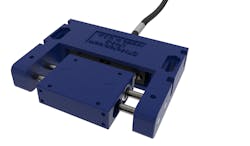
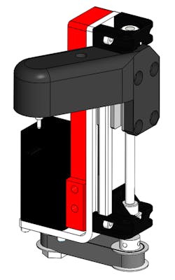
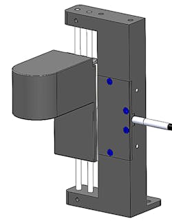
Other developments include variable travel linear motion actuators. In this derivative the piezoceramic resonator is attached to a carriage on a linear bearing system and can drive the carriage with a force of 10 N along any length of track. The carriage can be moved at up to 200 mm/sec and can be controlled in 50-nanometer incremental steps. This embodiment of a linear piezomotor system offers a useful design solution for very precise 3D-biomedical printing applications.
Piezomotors offer technical benefits and are now an affordable alternative to DC motors for rotary and linear motion requirements. They are direct drive and offer high precision with fast response times, plus good power density and light weight. With zero power to hold they offer the possibility of very efficient overall duty. They can be designed to offer low magnetic permeability for use in MRI fields, are immune from EM and RF interference, and have no emissions.
In short, piezomotors offer a unique alternative design solution for engineers to consider in a multitude of applications.
Nic Copley is VP of business development at Discovery Technology International.


