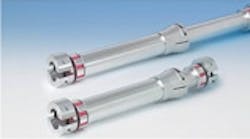
In applications such as printing and paper converting, where separated sides or ends of a moving machine must be synchronized, the most obvious solution is to physically connect them. Here, line shafts often fit the bill. These mechanical rods consist of a main body and servocoupling ends — to transmit torque over long stretches while compensating for the inevitable misalignment between the moving parts being coupled.
One line shaft manufactured by R+W America, Bensenville, Ill., is laterally quite stiff, so can transmit up to 35,400 in. lb over spans from 9.5 in. to 10 ft without center support. Called the ZA, these line shafting assemblies consist of two hydroformed stainless steel bellows, which compensate for misalignment with zero backlash and high torsional stiffness. Between the two bellows is straight cut-to-length tube. The connection between the bellows and tubing is safeguarded by a set of gimbals on each end of the shafting assembly. These gimbals transfer the tube's weight onto the coupling hubs, protecting the bellows from bearing its lateral load. A flanged connection between the tube and the bellows also allows for lateral mounting.
Electrical options
Another approach to line shafting is to forgo mechanical connections and electronically synchronize isolated parts that must work in conjunction. Over the last 15 or so years, many portions of the packaging and printing industries have adopted this approach. Called electronic line shafting, the technique has some key characteristics. First of all, electronic line shafting requires a motion-control program that establishes a master machine axis. (Sometimes, a virtual master axis is built into the control model.) Then, target positions are communicated over a network to each axis slaved to the master; these slave axes are commanded through a controller to follow moves prescribed for each master position and speed. The benefit is that the machine can be easily modified.
Electronic line shafting is particularly useful in registration applications — where separately applied colors or inks on an automated printing or packaging application are aligned with one another. That's because most modern printing operations make use of unwinder and winder axes, as well as four flexographic rolls per color applied to the paper, film, or plastic being labeled or marked. The latter pick up ink, project the image onto a mating roll, and then transfer that to yet another roll that contacts the material to be printed … while synchronizing with a final roll that presses the material to the printing barrel. Traditionally, these are mechanically synchronized — just as separate flexographic-roll sets are coordinated. Increasingly common are software programs, sensors, and controls that eliminate that requirement, as well as test runs and the like.
Benefits aside, electronic life shafting has one major drawback: Critical machine-cycle motion profiles can erode the most susceptible axis — the weakest link — so often the entire machine is slowed to protect this axis, which also reduces throughput.
To keep productivity high while protecting the most delicate motion axis, another arrangement devised by Schneider Electric, Palatine, Ill., is driven by controls and is called intelligent line shafting. Here, the master axis receives feedback from the others and calculates whether an individual axis will exceed its maximum speed or acceleration during the next machine cycle. Then the enabled master slows that axis down to stay within set limits. During noncritical motion phases, the virtual master then substantially increases the speed of that axis to beyond its previous set speed, to compensate for the slower segment.
For more information
R+W America
www.rw-america.com
(630) 521-9911
Schneider Electricelau.com
(847) 490-4270
Drive.Web Control Technologies
driveweb.com
(888) 667-7333
SEW Eurodrive
www.seweurodrive.com
(864) 439-8792
