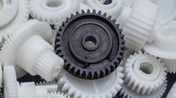
Engineers and designers can’t view plastic gears as just metal gears cast in thermoplastic. They must pay attention to special issues and considerations unique to plastic gears. In fact, plastic gear design requires attention to details that have no effect on metal gears, such as heat build-up from hysteresis.
The basic difference in design philosophy between metal and plastic gears is that metal gear design is based on the strength of a single tooth, while plastic-gear design recognizes load sharing between teeth. In other words, plastic teeth deflect more under load and spread the load over more teeth. In most applications, load-sharing increases the load-bearing capacity of plastic gears. And, as a result, the allowable stress for a specified number-of-cycles-to-failure increases as tooth size deceased to a pitch of about 48. Little increase is seen above a 48 pitch because of size effects and other issues.
In general, the following step-by-step procedure will create a good thermoplastic gear:
- Determine the application’s boundary conditions, such as temperature, load, velocity, space, and environment.
- Examine the short-term material properties to determine if the initial performance levels are adequate for the application.
- Review the plastic’s long-term property retention in the specified environment to determine whether the performance levels will be maintained for the life of the part.
- Calculate the stress levels caused by the various loads and speeds using the physical property data.
- Compare the calculated values with allowable stress levels, then redesign if needed to provide an adequate safety factor.
Plastic gears fail for many of the same reasons metal ones do, including wear, scoring, plastic flow, pitting, fracture, and fatigue. The cause of these failures is also essentially the same.
The teeth of a loaded rotating gear are subject to stresses at the root of the tooth and at the contact surface. If the gear is lubricated, the bending stress is the most important parameter. Non-lubricated gears, on the other hand, may wear out before a tooth fails. Therefore, contact stress is the prime factor in the design of these gears. Plastic gears usually have a full fillet radius at the tooth root. Thus, they are not as prone to stress concentrations as metal gears.
Bending-stress data for engineering thermoplastics is based on fatigue tests run at specific pitch-line velocities. Therefore, a velocity factor should be used in the pitch line when velocity exceeds the test speed. Continuous lubrication can increase the allowable stress by a factor of at least 1.5. As with bending stress the calculation of surface contact stress requires a number of correction factors.
For example, a velocity factor is used when the pitch-line velocity exceeds the test velocity. In addition, a factor is used to account for changes in operating temperature, gear materials, and pressure angle. Stall torque is another factor in the design of thermoplastic gears. Often gears are subject to a stall torque that is considerably higher than the normal loading torque. If plastic gears are run at high speeds, they become vulnerable to hysteresis heating which may get so severe that the gears melt.
There are several approaches to reducing this type of heating. The preferred way is to reduce the peak stress by increasing tooth-root area available for the required torque transmission. Another approach is to reduce stress in the teeth by increasing the gear diameter.
Using stiffer materials, a material that exhibits less hysteresis, can also extend the operational life of plastic gears. To increase a plastic’s stiffness, the crystallinity levels of crystalline plastics such as acetal and nylon can be increased by processing techniques that increase the plastic’s stiffness by 25 to 50%.
The most effective method of improving stiffness is by using fillers, especially glass fiber. Adding glass fibers increases stiffness by 500% to 1,000%. Using fillers does have a drawback, though. Unfilled plastics have fatigue endurances an order of magnitude greater than those of metals; adding fillers reduces this advantage. So engineers who want to use fillers should take into account the trade-off between fatigue life and minimal heat buildup.
Fillers, however, do provide another advantage in the ability of plastic gears to resist hysteresis failure. Fillers can increase heat conductivity. This helps remove heat from the peak stress region at the base of the gear teeth and helps dissipate heat. Heat removal is the other controllable general factor that can improve resistance to hysteresis failure.
The surrounding medium, whether air or liquid, has a substantial effect on cooling rates in plastic gears. If a fluid such as an oil bath surrounds a gear instead of air, heat transfer from the gear to the oils is usually 10 times that of the heat transfer from a plastic gear to air. Agitating the oil or air also improves heat transfer by a factor of 10. If the cooling medium—again, air or oil—is cooled by a heat exchanger or through design, heat transfer increases even more.

