The demand for sustainable, green energy has been pushing power companies to install more wind turbines. Those power companies naturally want to install turbines that are as efficient as possible with the lowest operating and maintenance costs and minimal downtime. One key component that helps achieve these goals in many wind-turbine designs are slip rings. These electro-mechanical devices transfer electricity from a rotating generator shafts to a transformer. Here’s a look at how material and mechanical engineers are leveraging technology and common sense to build a better slip ring.
Slip Ring Basics
In wind turbines that use a doubly fed asynchronous generator, the generator’s stator windings remain stationary and do not rotate. They provide approximately 70% of the turbine’s current. It travels by cables to a transformer and, because the stator does not turn, no slip rings are needed.
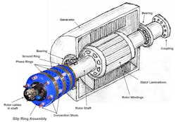
The slip-ring assembly mounts on the end of the generator shaft where it transfers current generated by the rotor windings to a transformer.
The rotor windings, which do rotate, generate the other 30% of the current—a significant portion. This current travels along three cables that run down the center of the hollow, rotating generator shaft. Each of the three cables attaches to a pair of studs that feed either the K, L, or M ring on the slip-ring assembly (i.e., two studs per ring). The slip ring assembly rotates with the generator shaft. A set of stationary carbon/graphene brushes, one for each of the three rings, picks up the current from the turning slip rings and sends it to the transformer. (The three rings let the slip ring transfer three-phase power.)
Connecting Rods
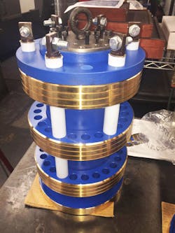
The three slip rings are isolated electrically but connected mechanically by six insulated connecting rods. The six rods come in three pairs, each pair a different length. One pair is long enough to reach the K ring (3.65 in. or 92.75 mm), another pair is a little longer to reach the L ring (8.81 in. or 223.75 mm ), and the last pair is long enough to reach the M ring ( 13.97 in. or 354.75 mm). Insulation on them prevents catastrophic flashovers. There is also a fourth ring, the ground ring, that protects bearings from stray electrical currents to prevent electrical damage.
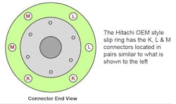
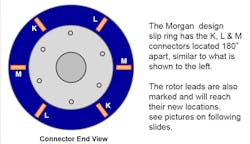
In traditional slip ring assemblies for wind turbines, each pair of connecting rods going to the same slip ring are located to each other (see illustrations below). This design calls for heavy counterweights to offset the naturally unbalanced distribution of connecting rods. At Morgan Advanced materials, engineers arranged each pair to be separated 180 deg. from one another so that equal size and weight rods are opposite one another. This balances the slip ring assembly, and becomes more important when using larger-diameter and heavier-stud connecting rods.
Traditional style slip rings (top) position the connecting rods next to each other on the slip ring assembly. On Morgan’s slip rings (bottom), rods for each ring are 180 deg. from one another for better balance.
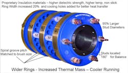
Morgan has also greatly increased the connection-rod diameters and improved the connection. This has been done by replacing the small-diameter threaded stud and nut with a larger flat surface and a bolted connection. The increased stud diameter and better connections greatly reduce the heat compared to the heat generated by higher resistance in small rods and poor connections in traditional slip rings.
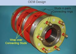
Many traditional slip rings have the connection studs wrapped in insulation to prevent dust from collecting. but the insulation inhibits cooling and traps heat. Using the right coatings and insulating materials on the studs provides an open-air design that allows improved air flow and better cooling, without fear of dust collection. A cooler slip ring can likely contribute reduced shaft and bearing temperatures, potentially even allowing for increased production in hot weather conditions.
This traditional steel slip ring design has a red wrap over the smaller diameter rods which are in pairs and have threaded connections. The wrap traps.
Bronze Rings
Traditionally, slip rings have been solid steel, the most affordable option. However, bronze is now being recognized as more efficient for some applications, reducing failure rates and the amount of time technicians spend in the turbine while increasing uptime.
Compared to steel, bronze dissipates heat more effectively, letting the slip rings run cooler. It also means less heat-related damage to the carbon brushes. In addition to these benefits, if the brushes are made of the right materials, they build up a friction-reducing patina on the bronze ring by rubbing against it. The patina reduces frictional wear on the brushes and eliminates extraneous conductive dust. Current can travel on the dust and can flow to places where it causes damage and destruction.
This Morgan slip ring has larger connecting studs and more insulation on them. This lets the designers eliminate the wrap to keep off dust and give the assembly a cooler, open-air design. The designers also added cooling holes on the wider rings.
A critical component in making brushes and slip rings last a long time is that of reducing friction. The film or patina formed by an electrochemical reaction between the brush material and ring material, although only angstroms thick, can be a critical component in reducing friction.
Another way to avoid dust is to specify slip rings with specialized paint coatings. These coatings prevent brush dust collecting and sticking to the slip ring, reducing the undesirable tracking of current. The bronze also puts less wear on the brushes.
There are a few properties engineers should consider when choosing or retrofitting slip rings. First, they should find a supplier that has invested significant research and development into insulation materials. Improved insulation will have higher dielectric strength, better resist higher temperatures, and possess “non-stick” properties. These properties keep conductive dust from collecting and current from flowing where it is likely to cause damage or destruction.
Slip rings can weigh from 50 to 400 lb and have outer diameters ranging from 5.5 to 12 in. They turn at 1,400 to 1,800 rpm and typically transfer 575 to 690 V.
Secondly, the width of the slip ring is critical in handling thermal loads. The wider the ring, the more material it contains, and the more it will stay cool. Morgan’s material engineers, for example, have developed a bronze slip ring with a 20% increase in width for additional thermal mass. They also put cooling holes through the rings for better heat transfer. A cooler slip ring likely reduces shaft and bearing temperatures, potentially allowing for increased production of electricity in hot weather.
Although the initial outlay for bronze is higher, there is no question that it prolongs the life of brushes and reduces temperatures, making it a worthwhile investment in the longer term, and a greater payoff in terms of whole life costs.
Slip rings assemblies also have a fourth ring, the ground ring. It does not have constant current flow and therefore do not typically have a spiral groove. The purpose of the ground ring and brushes is to shunt any current away from bearings to protect them.
Brushes
As the slip ring is spinning, brushes pick up current from the three rings. They are typically made of low-friction conductive carbon materials including copper graphite, silver graphite, natural graphite, electro graphite, resin-bonded carbon, and pitch-bonded carbon.
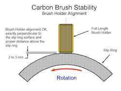
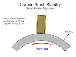
The brushes are held in position by static brush holders. The holders are equipped with springs which let the brushes move while staying in contact with the rotating slip ring. These components are critical for keeping the brushes stable, which makes a difference in performance and wear rates. So, having reliable, durable brush holders is key to eradicating costly downtime.
When brush holders are not at the right height or angle, or are incompatible with the brushes in use, the slip ring can undergo grooving—a type of scarring of the metal. Grooving is caused when brushes lose contact with the slip ring and create arcing. Arcing damages slip ring in a similar way to how grooves are cut during electrical discharge machining. Loss of electrical contact and arcing can also destroy circuit boards, which can cost nearly as much as a slip ring assembly.
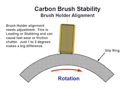
These images show the different brush holder alignments and how misalignment or incorrect height can cause brush instability and loss of contact. Stubbing is when a brush is angled with the bottom (brush face) pushing against rotation. This creates higher friction forces and can cause the unstable brush to easily bounce and lose contact with the slip ring.
If brushes are unstable, another fault of the holder, it can lead to friction chatter. This causes a loss of contact between the brush and slip ring which can lead to arcing and damage to the rings. Even worse, friction chatter can cause complete flashovers, which are high-current electrical short circuits that can destroy the slip rings and other components in the generator brush box. It can also harm workers if they are too close. This damage can lead to costly downtime.
The instability of brushes leads to excessive brush and slip ring wear, which can produce conductive dust. This dust can cause current to track and flow in places where it is not desired, again increasing the risk of a destructive flashover.
Brush materials must also be chosen to be compatible with the slip ring material. If they aren’t, the brushes wear quickly and generate lots of dust. Besides sidetracking current to where it shouldn’t go, the dust increase cleaning times. To avoid dust, technicians can choose brush materials that contain less resin. When there is little dust, it can be removed by redirecting cooling air.
Spiral Groove
Many slip rings have spiral grooves machined into their outer diameters. They are as wide as the brushes. With the proper pitch to the spiral groove, the surface area of the slip ring remains constant as the air gap rotates under the brush faces. This is important as it maintains a constant brush pressure and a constant amperage per square inch (APSI) of carbon brush touching the slip ring surface.
APSI can also be referred to as current density. With an improper pitch to the spiral groove, current density and brush pressure vary—i.e., they do not remain constant from brush to brush as is desired. Proper axial brush holder adjustment is also important in keeping the brushes located on the correct part of the slip ring surface.
The purpose of the spiral groove is often misunderstood. Many think of it as a cooling or dust groove. While the spiral grove can aid in cooling and dust removal, the significant and intended purpose is electrical. The groove is a rotating air gap which forces current flow to change as the air gap rotates and moves beneath the brush faces. This constant change in location of the current flow in the brush faces helps prevent selectivity.
Selectivity is when the current chooses a path of least resistance which can cause some brushes to wear at accelerated rates due to increased current flow and heating. The higher the current flow, the more heat there is in that brush. This means there is a lower resistance in the carbon, and then even more current flow, creating a snowball effect where one problem exacerbates another. Carbon is unique in that as temperature increases, resistance is lowered; this is why the above is true. The spiral groove is effective in forcing the current to constantly move within the brush faces, which helps the brushes carry the same loads and thus wear at more similar rates.
Engineers and technicians will continue to improve wind turbine performance while making more durable and less prone to maintenance problems and downtime. This will help make wind power a more viable and cost-effective means of generating emission-free electricity.
George Finley is wind segment manager at the Electrical Carbon business of Morgan Advanced Materials. For more information on slip rings and materials, call +82 53 615 1061 or visit www.morganelectricalmaterials.com.

