Download this article as a .PDF
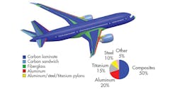
Laminated fiber-reinforced composite materials are being used in more and more engineering applications. These materials have excellent strength-to-weight ratios and the manufacturing processes that create them have been greatly improved since these materials were introduced. The popularity of these materials can be seen below in an image of the various composites used to construct airframes in modern aircraft.
Performing structural simulation on composite structures is crucial in designing components made of these materials, but laminated fiber-reinforced composites are some of the most challenging structures to model with FEA. Factors that complicate the construction of finite element models of composites include:
- Composite construction consisting of stack-ups of thin laminae.
- Each lamina having unidirectional or woven fibers in a matrix.
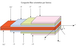
- The fibers’ directions in each lamina can and normally having different orientations, which are used to tailor the composite’s strength and stiffness to match the loading environment (see image below).
A micromechanical approach for modeling composites, where the mesh is fine enough to model individual fibers, is typically not feasible and thus usually limited to research studies. Most practical composite structural analysis is performed using a macromechanical approach in which the smallest modeled component is a lamina. Even macromechanical models can be extremely difficult to create due to the small dimensions of a lamina and the difficulty in characterizing material property orientations. There are several general macromechanical approaches used to build composite configurations: layered shells, layered solids, and solid elements (one or more element per lamina).
Using layered shell elements is the most efficient approach to both generating composite finite element models and solving them. Layered shells use classical lamination theory to model the structural response of an entire laminate based on the definition of each individual lamina. The main assumptions are that displacements are continuous across lamina boundaries (no relative slip between lamina), and the laminate is governed by shell theory. These assumptions result in a linear through-thickness variation of strain but stress variation can be discontinuous at lamina boundaries (as represented below).
Note that a single layered-shell element contains the entire stack-up. Classical lamination theory creates the stiffness of the element from individual lamina stiffness, but overall element response is governed by shell theory. However, once the layered shell’s degrees of freedom are calculated in the finite element solution, individual layer stresses and strains can be obtained, and even interlaminar shear stresses can be evaluated.
Using layered shells to model composite structures works well for thin bodies, but as the part becomes thicker, the shell theory’s assumptions become a limitation. For example, thin shells should have a ratio of the radius of curvature (or smaller span length for flat shells) to the thickness of 20:1 or greater. Thick shells may be valid down to a ratio of 5:1. For layered geometry with smaller ratios, the second approach of using layered solids is more accurate. Layered solids can model several laminas, and unlike shells, the finite element model can use multiple stacked elements to create the full composite section. The three-dimensional formulation predicts the full strain and stress tensors, but this approach likely requires more work in setting up the model and solving the analysis.
There are many challenges to using layered solid elements. For example, the solid mesh must be created with the stack-up direction within the element specified correctly. In shells, the finite element model consists of the mid-surface of the shell, so the composite material’s stack-up direction is defined as normal to this surface. With solid elements, the through-thickness stack-up direction can be in any direction within the element, and the finite element code may have requirements on which direction can be the stack-up direction. Solid layered elements can be stacked, so defining layered sections may require significant manual labor and requiring brick meshing that can be tedious to generate for complex geometry.
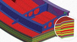
The third approach is to use one or more solid elements within each lamina. This is the more accurate approach because each element is contained within one lamina and thus no assumptions are needed to model layered stiffness. Detailed three-dimensional stress and strain tensors can be directly calculated without any special assumptions or approaches. However, an obvious drawback is that it will likely take an extremely large number of elements to model the composite structure. And, like any composite model, directional material properties must be defined and local features such as ply drop-offs and inserts complicate the modeling effort. An example is shown below.
Constructing composite finite element models is not the only challenge when analyzing composites. Obtaining and evaluating the results typically requires significant effort. Stresses and strains in each composite layer will be calculated, and each layer must be evaluated to determine the composite’s critical regions. Each layer, due to the fibers’ orientations, has stiffness different characteristics based on orientation, such as along or perpendicular to the fibers. Thus, the stresses and strains also vary in these directions. As a consequence, it takes more work to review and evaluate results in different directions in each layer to determine the overall response of the structure and identify critical regions.
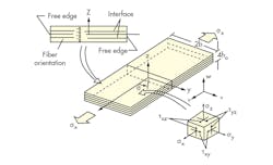
Interlaminar stresses are results unique to layered composites. They are defined by the out-of-plane normal stress component and two out-of-plane shear stress components that describe the response between lamina. Interlaminar stresses are important because they can be related to delamination, the common failure mechanism in composites. Calculating interlaminar stresses usually requires additional assumptions and post-processing techniques.
The interlaminar stresses are the out-of-plane stresses σz, τxz, and τyz. A tensile interlaminar, σz, along an interface tends to separate layers, while the interlaminar shear stresses τxz and τyz tend to shear apart the interface in their corresponding directions.
The challenge of analyzing composites is daunting. However, over the past few years, special-purpose composite pre- and post-processors have become available to assist in building and evaluating complex composite finite element models. These codes can efficiently generate all three types of composite models that were discussed. This eliminates much of the user-intensive manual work. And they can assist in efficiently evaluating results.
An example of a composite model generation tool is ANSYS Composite PrepPost (ACP). It works regardless of whether a shell or solid mesh is required and always starts with meshed surface geometry. The composite geometry and mesh is created from the surface using defined stack-up definitions that include material, thickness, and orientation information. Ply tapering and ply drop-offs can readily be incorporated. ACP supplies a direct model review, where the stacking is checked and changed on the fly. An example is shown below.
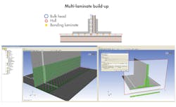
In ACP, an imported shell element model acts as the starting point for building the composite. Users create composite fabrics consisting of a material and a thickness. They then define laminate consisting of an assembly of fabrics. Fiber orientation is supplied using local rosettes and the ply sequence is specified for groups of elements. Ply drop-offs are defined and ACP automatically creates the layered geometry by connecting appropriate layers beyond the drop-off location. Laminates can be built-up on both sides of the original shell surface, allowing for efficient creation of complex composite geometry (as shown below).
ACP can generate layered shell, layered solids, or a specified number of solid elements per lamina to the ANSYS finite element program. The composite model can readily be combined with non-composite geometry, such as adjacent structures or even inserts, by dragging and dropping several component models into one analysis model. The composite model is then analyzed using normal FEA techniques, defining loads and boundary conditions, and solving the structural analysis.
Tools like ACP greatly increase efficiency during post-processing of the results from composite analysis. In composite analysis, the stress and strain tensor in each element’s layer is calculated based on its local orientation. In addition to sifting through large amounts of data, the task of interpreting composite stress and strain results must be addressed. Composites have multiple failure mechanisms, such as fiber failure, matrix cracking, and delamination of layers, so determining the structure’s critical regions is often performed using failure criteria.
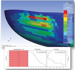
Common failure criteria, such as Maximum Strain, Maximum Stress, and Tsai-Wu, calculate a scalar quantity based on a combination of the stress or strain components to determine the failure limit. When post-processing using ACP, failure criteria can be selected, and it can plot the worst-case failure criteria over all the layers in each element. Critical elements can be identified, and the stresses, strains and failure criteria values plotted through the layer stack-up to determine an element’s critical layer.
So, although modeling composites in finite elements can be difficult, new special-purpose and user-friendly composite tools alleviate much of the tedious modeling effort that was required in the past.
