A history of gripping and gripper technologies and the available options for today's engineer
What is a robot without its arm or means to grip and move objects? Not much. Technically, robots have existed for at least 100 years. Their rougher mechanical movement is relatively easy to generate, particularly with electric motors or pneumatics. However, it's only been over the last 40 years that mechanical motion precision, controls, sensing, and feedback have advanced enough to refine robotic handling to the realm of indispensable.
You see, unlike more basic kinematic linkages, robotic arms by definition have multiple degrees of freedom that must all be synchronously directed in a kind of electromechanical (or servofluidic) ballet.
In fact, the feedback required to actuate sensitive robotic grippers — ones responsive enough to the environment to be of practical use — is something of a new possibility: Therefore, it's only been 25 or so years since the first practical grippers went into production for real industrial applications.
Gripper history lesson
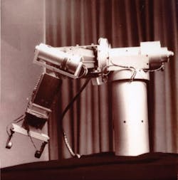
It all began in 1969: After much toil in the school's machine and computer labs, Stanford University mechanical-engineering student Victor Scheinman developed his Stanford arm, an early robot that would come to be known as the first readily controllable gripper.
Predecessors such as the Hydraulic Stanford arm were effective and fast, but known for being uncontrollable and even dangerous.
In contrast, Scheinman's better-behaved Stanford arm was steerable by Stanford-lab computers in six full degrees of freedom; dc electric motors with gear reducers and harmonic drives generated its motion.
By the early 1980s, rougher gripper designs inspired by the Stanford arm (and made possible with increasingly powerful microchips) were in mass production, and used in heavy industry.
Though many Stanford-arm feedback and control elements were copied (feedback tachometers and potentiometers sent speed and position to controllers) most early industrial arms were powered by air, and used for automotive manufacturing. Coincidentally, that legacy survives: Many of the latest gripper advancements come from the field of fluid power, and the majority of grippers are still pneumatic.
Gripper evolution began with parallel varieties
The original Stanford arm included something called a parallel gripper; this ubiquitous design, still common today, consists of two straight-bar fingers actuated to simply slide together or move apart to grip and release objects. “Two-finger grippers are most commonly used in industry today, because of their stroke versatility,” says Jesse Hayes, product manager of automation components at Schunk Inc., Morrisville, N.C.
A variation — the two fingered angle gripper — came in the late 1970s. Each of the two fingers in this design swings on a pivot point, closing like a gate or lobster claw on target objects.
What's the difference between parallel and angle action? Parallel jaw action simplifies finger design, and force remains the same throughout the stroke — unlike some two-finger angular grippers. The parallel design also offers distinct design options: Grippers with a direct-acting piston and wedge allow for shorter stroke and high grip force, to 10,000 lbf. By comparison, straight direct-piston grippers generate slightly smaller force, but offer longer strokes, to 24 in. in some cases. “I would estimate that 60 to 70% of applications end up using parallel grippers,” adds Hayes. Many of these units leverage fluid power as well, though some grippers are offered in both pneumatic and electromechanical versions.
The next gripper innovation came in the late 1980s: A three-finger grasper, developed at the Massachusetts Institute of Technology was licensed to spinoff Barrett Technology Inc., Cambridge, Mass., in 1990. The design, now called the Barrett hand, embeds servocontrollers, software, communication, and four brushless motors. Two fingers have an extra degree of freedom, with 180° synchronous lateral mobility for lots of ways to grasp.
Remember that two-finger grippers perform best when dedicated to a single specific task — and must be swapped out for other grippers on a turret if parts or target shapes change. In contrast, the latest BH8-series Barrett hand performs the functions of several custom parallel grippers. Here, Windows-based BHControl user interface plus C-Function Library and firmware help the gripper adapt to new situations.
As it happens, late last year, Barrett Technology also licensed the polymer-based SDM Hand, a grasper developed by Robert D. Howe of Harvard University's School of Engineering and Applied Sciences, and Aaron Dollar. This robotic hand has fingers with flexible joints, so it conforms to and grips objects ranging in shape and mass — without excessive force or requiring perfect positioning. Barrett expects production SDMs availability by 2011.
In fact, though three-finger grippers have existed for some time, they're only now being applied more widely. “In the more immediate future, as assembly and robots become more flexible, able to handle a wider range of parts without tooling changeover, engineers will indeed start to see products like our own SDH hand, a three-finger device, taking a larger role in gripping … or at that point we would describe it as grasping,” says Hayes of Schunk.
Gripper alternatives: Non-finger variations
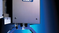
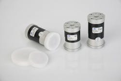
Air-powered grippers that aren't fingered types, or more or less modeled after the human hand, typically use suction and flexible cups to grasp, instead — and usually handle very breakable or flimsy objects. Case in point: Sensitive SCG grippers from Schmalz Inc., Raleigh, use sucking air current to separate ultra-thin sheets of foil, even before the gripper contacts them. Only one intermediate layer is gripped per cycle. For in-mold labeling, even foils thinner than 0.0012 in. can be attached to product packaging while retaining their shape. Here, the gripper's large contact surface prevents sensitive workpieces from being sucked in. In addition: Integrated vacuum generation boosts volume flow for secure gripping of even odd or porous materials.
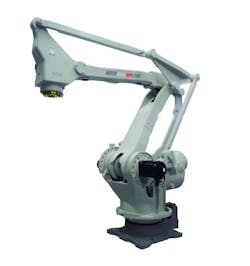
Suction grippers are installed at the ends of regular robot arms for when they handle items such as automobile windshields; otherwise, they're installed at the bottom of ceiling-mounted delta robots — the lightweight spideresque parallelogram design released in recent years from some patent limitations. Deltas fitted with suction grippers do delicate work, such as packaging cookies, moving semiconductor chips, and performing medical tasks.
Gripper functions to grip and rotate
Where pneumatics power grippers with traditional cylinders, instead of suctioning, multiple air supplies are usually required. This is certainly true for dual-motion units that both rotate and grip — another development of the last several years.
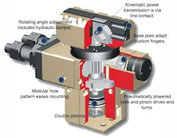
For example, DGP404 parallel modules made by Techno-Sommer Automatic, New Hyde Park, N.Y., grip and rotate — turning parts either 90° or 180° (with T-slot guides that absorb forces and moments) while a separate pneumatic connection activates finger-grasping action. In some cases, to boost efficiency, a mechanical retainer holds after pneumatics establish initial grip. The inspiration of the Stanford arm is still evident here: In the old breakthrough design, electromechanical brakes and slip clutches held joints in position (when the early-generation controller was busy directing other linkages) and prevented collision damage.
Another rotating gripper is a miniaturized unit from Schunk. Their RP unit produces and assembles minuscule components. A Schunk RM rotary module is combined with a pneumatic parallel gripper, which can be equipped with different ID or OD grip-force safety devices, for semi-custom designs. Combining rotating (“wrist”) action with gripping does require mechanical design modifications: In some cases, grip drives are fitted with longer piston rods to operate on rotary modules.
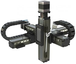
Besides robot arms and delta robots, a third mounting option for grippers is on Cartesian gantries; this setup is more common with fingered grippers. To ease mounting here, Schunk's rotators have standardized hole patterns to connect to adapter plates and Gemotec modules — the products of a manufacturer that Schunk acquired in 2006. This makes combining grippers with linear units easier, to quickly build on pick-and-place, gantry, and complete-function units.
Taking grippers to the next level: Give ‘em a hand
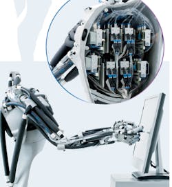
To date, use of robotic hands in industrial production has been restricted to rugged two and three-finger grippers. However, Festo Corp., Hauppauge, N.Y., is taking it to the next level: Mechatronics and bionics combine in the company's Airic arm, so 30 pneumatic muscles leverage artificial, laser-sintered polyamide ulna and radius, metacarpal and finger bones, and shoulder joint and bone. (Festo already manufactures the fluidic muscles for real-world applications.)
When these elastomer tubes (with integrated aramide fibers) are filled with compressed air, diameter increases and length shortens to do work. One advantage over the human version after which these are modeled: The muscles require no energy to hold weight in place after moving. Pressure and length sensors monitor tensile forces and contraction; a mechatronic regulator distributes pressure to model human kinematics, rapidity, force, and refinement.
A smaller but similar design is made by London-based Shadow Robot Co. Ltd., a newer startup company: Their smaller fluidic muscle and motor-based hands have been sold to a few government and research organizations.
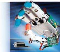
Meanwhile, other research-level developments continue. The German Aerospace Center (DLR), a generator of robotic-hand ideas, in cooperation with the Harbin Institute of Technology (HIT), recently developed a robotic hand with the strength and dexterity of a human hand: Three fingers grasp even conical parts, and a thumb gives support. The fingers' four joints have three degrees of freedom, and the thumb has four.
Each joint also features a contactless angle and torque sensor that require high resolution — and quick comparisons for the field programmable gate arrays (FPGAs) of setpoint and actual values — so a realtime-capable, 25-Mbps, high-speed bus embedded in the robotic hand transfers that data. Control of all these linkages also falls to the bus.
Better microprocessors benefit the new design: In 1969, the Stanford arm programming simplified the links and trajectories to speed up control computations. In contrast, only three external serial leads connect the hand to a HIT-DLR control processor. Also: Early robotic fingers were moved using cable pulls, but the HIT-DLR hand has motors fitted directly in the fingers. In short, 12 analog Hall sensors and electronically commutated dc motors (Faulhaber EC motors) made by MicroMo Electronics, Inc., Clearwater, Fla., are installed through the hand.
HIT-DLR developers also hope that their hand soon finds wider use. To that end, a signal processor on a plug-in PCI card is integrated for a standard PC, so the hand can be controlled from a software window. Sensor data is displayed on-monitor; hand connections to the computer are also optimized for industrial use.
SPECIALTY GRIPPER APPLICATION EXAMPLE: Cappers close the deal
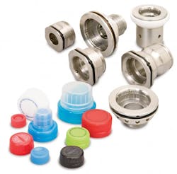
Bottle capping is one application for which fingered grippers are inappropriate — so most all capping machines today use custom-made chuck grippers.
Chucks are metal pieces that feature a cap-shaped hole or tap. On their inside surface, pins provide temporary holding as caps are screwed into place. If a chuck does not properly grip its caps, problems arise: Dropped and cocked caps, tamper band rollover and broken tamper bands … these problems lead to leakage, low line efficiency, and high scrap rates. However, the biggest challenge in capping is properly applying caps to bottler-specified torque levels. With PET material costs on the rise, many manufacturers are switching to lower-profile caps. While greener, these caps are more susceptible to damage, so require headsets and chucks with higher precision — so the caps fit more exactly into the tap.“The grip on our caps is controlled by positioning several pins in the chuck to hold the cap,” says Angela Leng of Warner Electric of Altra Industrial Motion, Braintree, Mass. Warner chucks were recently installed for a PTOC low-profile cap conversion done by Coca Cola. “We have replaced many mechanical jaw assemblies (which wear quickly) with fixed-jaw assemblies; mechanical customers that can switch dramatically reduce chuck maintenance,” concludes Leng.
In his writings, science-fiction writer Isaac Asimov proposed three Laws for Robotics: That a robot should not injure human beings or allow them to be harmed; that a robot must obey human orders except where such orders would conflict with the First law; and that a robot should protect its own existence after obeying the First and Second laws. The problem with this in real manufacturing situations is that preventing robots from injuring people typically requires a jungle of fences, cages, and curtains.
One solution: ABB Inc., New Berlin, Wis., has developed a controller called SafeMove, to help manufacturers meet safety standards while doing away with more primitive physical barriers. In short, the controls spring into action when a person enters a robot's work area, making the robot immediately cower into safe mode and slow all operations.
End effectors and grippers are required by law to include safety functions that prevent dropping a load, even during loss or change of energy supply — whether electrical, hydraulic, pneumatic, or vacuum. SafeMove controls can prevent this and limit the hazardous swapping of detachable grippers in the presence of a human.
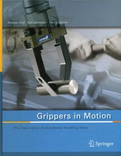
One excellent reference is Grippers in Motion: The Fascination of Automated Handling Tasks. Written by Schunk engineers, the illustrated book is available through amazon.com. Grippers in Motion provides a comprehensive, practice-oriented guide to the fascinating details of automation processes involving gripping and manipulation. From the publisher: "This intriguing and colorful book leads the reader from the history of automation and robotics to the fundamentals of the gripping process as well as the interaction of the gripping process with individual workpieces. Boundary conditions and initial situation of the gripping process are defined, and how subsequent motion follows gripping is shown."
Also contact or visit the companies that contributed information and images for this article:
-
PBC Linear
(800) 729-9085
LAT.pbclinear.com -
Schmalz Inc.
(919) 713-0880
www.schmalz.com -
Techno-Sommer Automatic
(800) 819-3366
techno-sommer.com -
Barrett Technology Inc.
617-252-9000
barrett.com -
MicroMo Electronics Inc.
Faulhaber Group
(800) 807-9166
micromo.com
-
Festo Corp.
(800) 993-3786
www.festo.com -
ABB Inc.
(262) 785-3400
www.abb.us -
Shadow Robot Co. Ltd.
44 (0)207 700 2487
shadowrobot.com -
Motoman Inc.
(937) 847-6200
www.motoman.com -
SCHUNK Inc.
(800) 772-4865
www.schunk.com
