Keeping Gantries on the Straight and Narrow
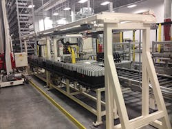
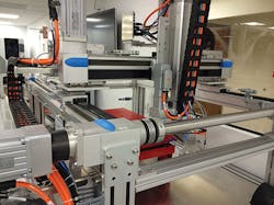
Gantry systems, sometimes referred to as Cartesian robots, are ideal positioning systems for automated transfer lines. In this type of manufacturing process, a continuous or indexing conveyor transfers parts from one gantry station to another. Each gantry station along the conveyor line manipulates a tool with respect to a part to perform manufacturing operations such as machining, gluing, assembling, inspection, printing, or packaging.
Clearly, the reliability of each machine in a transfer-line operation must be extremely high to minimize downtime, because downtime in one machine may bring the entire transfer line to a costly stop. In addition, gantries include many critical elements, such as a controller, amplifier, motor, coupling, actuator (such as a ballscrew, belt, or linear motor), rails, slide, base, stops, encoder, and cables. The reliability of the entire gantry system is the statistical sum of all components’ reliabilities.
For high system reliability, each component must be sized to ensure that its loading during operation will not exceed its rated values. While sizing each component may be a straightforward engineering task, as recommended by the component manufacturer, linear-rail failure modes are somewhat more complex. They depend, in addition to load-carrying capacity, size, and precision, on their precise orientation in space.
Misalignment problems
Almost every linear-rail manufacturer agrees that misalignment leads to problems. For example, according to Rollon Corp., “Of all the factors that contribute to the premature failure of linear bearings, misalignment ranks near the top of the list.”
Similarly, NSK classifies rail misalignment failures that include: flaking: removal of material from the rail surface; wear: results of excessive friction; indentation: balls deform the rails; and damaged parts: deformed rails due to balls falling off rail grooves.
Common root causes of rail misalignment include lack of flatness, straightness, parallelism, and coplanarity of linear rails. These causes could be minimized or eliminated by proper assembly and alignment techniques, which, in turn, minimize rail overload. Other root causes of linear-rail failure include insufficient lubrication and ingression of foreign particles, which can be mitigated though proper sealing and periodic lubrication. While important, they are beyond the scope of this article.
Alignment basics
Gantry rails typically include recirculating ball bearings that are pre-loaded in their running grooves to provide high stiffness. High stiffness and low-moving mass are critical gantry characteristics, because they define the lowest system natural frequency. High natural frequency, on the order of 150 Hz, is required for high position bandwidth. High position bandwidth, on the order of 40 Hz, is required for high dynamic accuracy. High dynamic accuracy, such as constant velocity with a few microns’ position error, or low settling time, on the order of a few milliseconds to a submicron settling window, are required for high part quality and high throughput, respectively. These performance characteristics are typically required under conflicting effects of high acceleration and smooth motion in processes such as PCB inspection, inkjet printing, and laser scribing.
To ensure high gantry stiffness—on order of 100 N/µm—bearings are preloaded. However, any misalignment between the two gantry sides on order of 10s of microns, either in vertical (flatness) or horizontal (straightness) orientation, may dramatically increase bearing load. That, in turn, may lead to catastrophic failure due to balls falling out of the bearing grooves or deep indentations in the rails. Smaller bearing deformations may still reduce bearing life substantially.
To align linear rails with 10s of microns precision over long travel lengths (on order of 1 to 3 meters) requires expensive tools such as a laser interferometer and special fixtures. These tools may not be readily available to the typical end user or system integrator. Without these tools, rail misalignment may be the root cause of low system reliability, high maintenance costs, downtime, and short system life.
Fortunately, there are various field-proven misalignment compensation options that may not require extensive alignment tools, yet provide high value by reducing the potentially harsh effects of rail misalignment. These misalignment compensation devices become integral parts of the gantry frame and provide the necessary degrees of freedom to prevent bearing overloads in various gantry rail mountings and axis-drive configurations.
Kinematics of misalignment
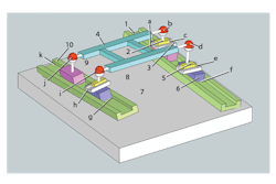
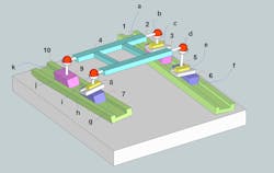
To understand how a misalignment compensator works, one must understand the compensator’s kinematic characteristics as part of its gantry system. As an example, the accompanying 3D gantry diagram shows four supports. The bases of stages X1 (connected link 10) and X2 (link 1) are shown exaggeratedly misaligned in pitch, yaw, and roll with respect to each other as well as in flatness and parallelism. Assume the left X1 carriage (9) is the motorized master, and it has a spherical joint (j) that supports the Y stage (4). The opposite motorized right X2 stage (3) has one spherical joint (b) and one linear slide joint (c) which support the Y stage. The other X carriages (7 and 6) are idlers and also support the Y stage by a spherical joint and a linear slide.
Then counting the total number of degrees of freedom and subtracting the total number of constraints, the result is 1 degree of freedom. This means that only the master X axis can move independently and all other links will follow. In this case, if another independent motor drives the other X, an excessive load on the rails may result. This is an undesirable configuration for long Y stages and, therefore, engineers must make corrective changes to let the second X stage move independently from the first X stage.
Adding another degree of freedom to the system, such as for the X slave, means adding another degree of freedom to one of the joints. A common fix in such configurations lets one idler slide have a degree of freedom in the Z direction, for example, between spherical joints d and slide joint e.
The result will be a kinematic mount for the Y stage at joints b, j, and i, accommodating the 3D orientation of the stage 4 plane without any constraints. However, to prevent support of stage 4 at only three corner points, common practice is to add some compliance in the Z direction between joint d and slide e to take some of the load. In some cases the flexibility of link 4 may be sufficient; in other cases, a compliant Belleville washer may be used.
Compensator designs
Let’s review two misalignment-compensator designs. One is a compounded revolute joint with a linear slider joint, for a 3D gantry configuration. The second is an integrated revolute joint with a linear flexure joint for a 2D gantry configuration. In the 2D version, assume that the gantry rails X1 and X2 are coplanar.
Compounded-joints design. Consider a gantry application in a can-manufacturing process. The gantry uses two Festo belt-driven stages (type EGC-180-TB) that support a robust weldment frame on four slides. A servomotor drives each gantry stage in a master-slave configuration. A belt drives one slide of each stage, and the other slide is an idler.
The stages, assembled by the end user, experienced premature failure at the stage’s bearing. The problem was corrected by adding four readily available standard spherical joints mounted on four linear slides to the four slides of the two gantry linear stages. To match the configuration to the previously discussed gantry, one slide was “grounded” with a locking plate. The redesign completely resolved the problem.
The disadvantage of using such a compensator, however, is a substantial increase in height, which may require changes in the Z stage.
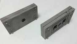
Integrated-joints design. An integrated misalignment compensator may be used in 2D gantry configurations. The design includes two plates. One plate has mounting holes to the gantry X slide and the other plate has mounting holes to the base of the cross-axis Y stage. A bearing at the center connects the two plates.
In addition, one plate includes a flexure that provides a linear degree of freedom in the Y direction. To use the same component for all joints, two bolts may be used to “ground” the flexure linear degree of freedom and retain only the rotational freedom of motion between the two plates. The flexure is designed to operate at maximum deflection below the fatigue limit.
Finally to prevent, in the case of 2D gantry configurations, from loading the flexure in a bending moment about the Y axis, four retaining bolts take up the moment loads.
The advantages of this design include integrated components, low profile, compact size, and ease of assembly to existing gantry stages in less than 15 minutes.
Misalignment tests
To see how compensators perform in the real world, we constructed a test bed for measuring misalignment forces and precision in gantry rails.
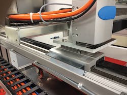
The gantry consists of two Festo belt-driven stages (model EGC-120-TB). A servomotor and gearbox drive one belt stage, X1. A rigid coupling to X1 drives the other belt-driven stage, X2. This is a common gantry configuration often used for cost savings in low-accuracy positioning applications.
To simulate the effect misaligned rails have on gantry performance, the two X stages were mounted at an angle of 2 mm over 1 meter of X travel. Tests then determined system precision and bearing resistance force with and without misalignment compensation. A laser interferometer measured the effect of the compensator on positioning accuracy. Bearing resistance force was tested by motor current. Here are the results.
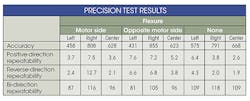
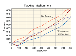
Precision tests. The graphic shows typical laser interferometer results for two precision tests—with and without misalignment compensation. Both tests were taken at the same side of the gantry with the flexure mounted on the motor side. The accompanying table summarizes all results, including: unidirectional and bidirectional repeatability and position accuracy, including left, center, and right gantry positions, with and without compensator, and with a flexure either on the motor side or the opposite side.
The results indicate:
Bidirectional repeatability is on the order of 80 µm, with or without the flexure. It is an inherent backlash characteristic of all belt-driven stages. The compensator does not improve or reduce it in any way. Ballscrew gantry stages have much lower backlash and linear-motor gantries have virtually none.
Unidirectional repeatability with the belt-driven system is on the order of microns, with or without the compensators. Therefore, with proper two-end calibration (that is, removing the linear error) and higher-order mapping, accuracy of the belt driven gantry may be improved to the order of repeatability.
Finally, flexure location has virtually no effect on the precision results.
Bearing resistance test. Measuring motor current determined the electric current profile of the gantry drive motor without and with flexure compensators. The mean current value, 650 mA, with a compensator is symmetric in back and forth motion directions. On the other hand, as expected, motor current without flexure compensator shows a gradual increase up to 800 mA when moving into the converging misalignment “wedge.” The mean current when moving away from the wedge effect is constant at 650 mA.
Also tested was the mean current of a perfectly aligned set of rails. It indicated the same 650 mA value with the misaligned rails using the compensator. Therefore, adding compensators to a misaligned gantry reduces bearing loads to the same level as if the gantry rails were perfectly aligned—without losing accuracy.
Gantry Alignment Tools |
|
When positioning-system manufacturers build a gantry system, they typically use special alignment tools during the assembly process to ensure they meet force, precision, and life specifications. Laser interferometers are frequently used for alignment of machines to precision on the order of microns and arc seconds. For example, a laser interferometer from Renishaw helps align gantry rails’ flatness, straightness, and squareness. Other tools, such as alignment lasers from Hamar, use rotating laser beams as precision reference planes in space with sensors placed on the moving slide. Adjusting rail-leveling screws, or shimming under the rails, brings the rail or stage to the desired orientation. Leveling of rails to high precision may take days or weeks depending on the accuracy level, size, and configuration of a machine. For lower-accuracy alignment requirements, various mechanical components are used, including electronic levelers, dial indicators, straight edges, and parallel beams. With these, technicians align the master rail with a dial indicator against a precision mounting surface or straight edge. After one rail is tightened to its required precision, a slide is guided along while the bolts of the second floating rail are tightened, using a dial indicator or a guiding slide. Regardless of the alignment method, it must ensure that residual misalignment will not exert forces on the stage rails, which may result in short life or a catastrophic failure. |
