Virtual modeling: Measure twice; cut once
Virtual modeling with software verifies components concurrent with other development tasks, while virtual integration can prevent inferior quality or missed deadlines caused by detecting errors too late in the game — during physical testing.
In short, virtual integration allows engineers to find and fix errors earlier, when they are easier and cheaper to fix. Modeling interactions reveals ambiguous or contradictory requirements. In addition, when individual component models are included in full-system models, it is easier to assess how component iterations affect overall behavior.
Three requirements
Let us consider embedded systems — good candidates for virtual integration. Embedded systems boost functionality for many designs, but at the price of increasing complexity. Normally, to confirm that an embedded system meets quality and design requirements, engineers must conduct time-consuming and resource-intensive design and code reviews, plus build complex test systems. Often, this verification represents more than 50% of total development cost.
To bring costs down, automotive, aerospace, and industrial engineers increasingly use virtual integration through model-based design, a process in which software improves designs and automatically generates code to streamline implementation. No actual system hardware is used; a program organizes and executes testing.
Virtual verification with model-based design has three parts.
-
An executable system specification is a full-system model or set of models that can be probed and investigated, usually through simulation. It includes models of relevant subsystems (control algorithms, mechanical and electrical components, hydraulics, and so on) detailed enough to reflect functional behavior. A system model should also include operating environment or plant models with actuator and sensor models for control applications, or transmission environment models for communications.
-
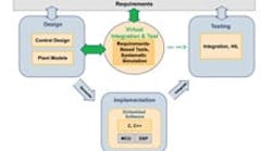
Requirements-based tests exercise executable system specifications to validate requirements. Tests are based on functional requirements that can be modeled as simulation input signals or sequences and, ideally, expected outputs. Some software can even show which parts of a model are actually exercised during a sequence of simulations.
-
The final element for virtual integration is a test and simulation executive — an environment for managing all tests, results, and running simulations. This environment is also used to author tests, compare those to models, and generate results for analysis. (Here, aerospace and automotive engineers often leverage computing clusters — multiple distributed computers — to complete many complex simulations in a reasonable timeframe.)
Typical versus model design
A development process using model-based design automatically generates code from detailed executable-specification models — so systems and their individual parts can be verified. First, written requirements are used to create the system-level specification, which in turn drives subsystem designs. Next, the subsystems are tested and integrated. Finally, the complete embedded system is tested; errors are detected as they are introduced.
Building the foundation
Most organizations utilize modeling, but few do it systematically, so the full benefits of simulation aren't realized. Where engineers buck this trend and insist on testable models, complete system models verify that requirements make sense, and that designs work.
In short: Plant parameters, inputs, and environmental factors vary, and time and budget constraints often limit how much variability can be incorporated into tests on actual hardware. On the other hand, centralized simulation accelerates individual tests and automates multiple tests across a range of input parameter values. In addition, limits and potentially destructive tests can be safely investigated virtually. Exploring all parameters in simulation also minimizes the number of critical tests that must be run in real time.
Individual component models may be necessary to complete a complex design. That said, there is no reason to wait until one component model is complete before modeling the larger system. By modeling a complete system in one software environment, engineers can quickly see how each component interacts with others and how integrated components behave once deployed.
For more information on model-based design, call (508) 647-7000 or visit mathworks.com. For information on Automation Studio, visit br-automation.com.
Third-party options
Model-based development is on the rise for industrial automation. As mentioned, consistent use of universal tools is key to getting the most from this approach. To this end, Automation Studio Target for Simulink from B&R Industrial Automation, Roswell, Ga., is software that implements advanced closed-loop controllers on the company's components.
First, models are constructed in the Simulink simulation environment (from The MathWorks) and then they are implemented on a B&R industrial controller at the push of a button.
Scalable to small and big projects, from single-axis applications to CNC and robotic projects, the tool is tailored to shape the motion of automated machinery — even systems that include HMIs and PLCs. In short, the software provides a Simulink blockset for variable and parameter exchange, and supports all B&R hardware.
Automation Studio's open architecture and its automatic code generation boost efficiency. Another advantage to this model-based design tool is that once simulation models and code have been created, they can be reused over and over — and updated for developing future machine generations at a relatively low cost. This helps engineers sustain interdepartmental know-how over the long-term, and reduces time to market.
