What’s the Difference Between Failure Theories?
This file type includes high resolution graphics and schematics when applicable.
Calculating stress can be a relatively easy task; you may even remember it from school. However, it’s much more difficult to determine all possible loading situations that cause stress. For this article, we’ll look at loading class, how it affects failure theory, and how that will change the factor of safety.
Note that this article provides an overview of design basics for those seeking general knowledge or an introduction to loading analysis. It does not attempt to cover all of the complexities of a loading analysis.
Load Class
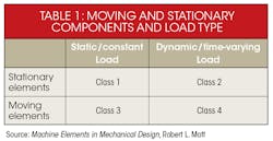
In general, the difference between loadings that will dictate if a design is safe will be whether it’s static or dynamic. While the stress is calculated, it is generally proportional to the loads. But the stress analysis is only as good as the quality of the information about the loading situations. This is broken into moving and stationary components and load type.
For example, in the midst of a quick assessment, someone could make a mistake and classify a bridge as a Class 1 load. However, once you consider the winds and traffic that act on the bridge, it would be considered a Class 2 load.
The difference between materials that will determine if a design is safe is whether they are ductile or brittle. The ductility of a material could alter the stresses considered in a design. For example, stress concentrations can be ignored for ductile material under a static load.
Ductile material—having more than 5% elongation before breaking—causes local yielding that reduces stress concentrations caused by geometric discontinuities. Brittle materials, on the other hand—those with less than 5% elongation before breaking and a difficult-to-define yield point—will need to include stress concentration with the calculated stress. There are exceptions, such as cast materials where inherent stress-raisers in the materials are so high, geometric discontinuities will have little additional effect.
Failure Methods
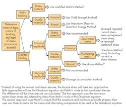
Differentiating between loading and material properties will help to reveal the types of stress. Obtaining this information is the first in a series of steps that will lead a designer to use the correct failure theory. Such a theory isolates the conditions in which a material for a specific application will fail. This prediction is the allowable stress, and it should be less than the actual stress. In the decision tree (Fig. 1), different situations will lead to the correct failure theory.
Failure theories cannot be compared side-by-side unless the same situations exist. Load, ductility of material, and stress types dictate the difference between failure theories.
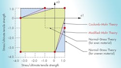
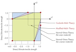
Figure 2 shows the stresses some that can be covered by static loading situations. Notice how a design must be less conservative (cover a larger area of stress) when dealing with brittle material—the line between Coulomb-Mohr’s versus modified Mohr’s. In addition, for uneven (materials that are stronger in compression than tension), using one of these methods over the normal-stress theory can allow for a more efficient design.
The principle stresses calculated by the failure theory (represented in Fig. 2 as σ1 and σ3) must fall within the area covered by the theory selected, not the opposite way around. Do not select the failure theory that covers the area with the stresses. This is because the different theories represent the behavior of the materials under that loading scenario.
Using the wrong loading, stress, or failure theory might lead to an inefficient design. This can lead to over-designing or using excessive material that leads to consuming more weight, resources, etc., which can give the competition an edge. However, overdesigning is the best-case scenario. The other option might lead to a design that is waiting for a catastrophic failure.
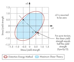
One common comparable example of a failure theory that does have the same loading situations involves the distortion energy method (DEM) and maximum shear stress. They will both work for biaxial and ductile material under a static load. However, the DEM is the most accepted and is often the failure theory used in FEA software.
If a customer asks for a design to be more conservative, or to use the maximum stress theory, the engineer must know the failure theory used by the software. Otherwise, it will be necessary to generate calculation by hand, spreadsheet, or a MathCAD-type program. Both theories use Mohr’s circle to calculate the information needed for the maximum shear stress and DEM (Fig. 3).
Factor of Safety
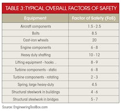
While the DEM generates an acceptable factor of safety (FoS), it is important to know the source of that information. Using published strengths of materials may sound safe (independent of the failure theory), but published properties could be the average or median value of where failures occurred. Designing to a published value, however perfect, could therefore yield a large number of failed components.
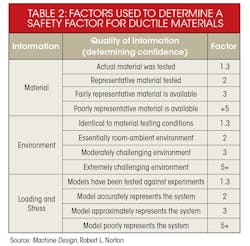
Guidelines will compensate for this average or median strength by increasing the design stress if using a handbook or manufacturer values. However, if strength values are obtained directly (the company tested the actual materials to be used), it might be acceptable to use the properties’ values. The level to which the material, stress, geometry, and failure analysis are known will determine the level of confidence in the design and can reduce the FoS.
The FoS is also changed by the ductility of materials and confidence in design material.
Ductile Materials
- FoS = 1.25 to 2.0, structures under static loads where there is a high level of confidence in the design data.
- FoS = 2.0 to 2.5, for dynamic loading with average confidence in design data.
- FoS = 2.5 to 4.0, for static structures or machine elements under dynamic loading with uncertain: loads, material properties, stress analysis, or environment.
- FoS = 4.0 or higher, static structure or machine elements under dynamic loading with an uncertain combination of loads.
Brittle Materials
- FoS = 3.0 to 4.0, for static loads with high levels of confidence on all data.
- FoS = 4.0 to 8.0, for static loads with uncertainty about: loads, material properties, stress analysis, or environment.
In summary, knowing how failure theory works and how the level of confidence can reduce the FoS will reduce material and weight in a design.
