What’s the Difference Between Beam Diagrams?
This file type includes high-resolution graphics and schematics when applicable.
Beam diagrams are used as a fundamental way to teach engineers the basic of static loading. Beams are structural elements that are able to withstand load by its resistance to bending. The bending force can be a result of external loads, weight, or the length of the beam. The beams experience a bending moment and a shear moment due to these loads.
Beams are classified based on their supports. Besides truss-supported beams, beams are classified in the following groups:
• Simply supported: A beam supported on the ends, which are free to rotate and have no moment resistance.
• Fixed: A beam supported on both ends, which are fixed in place.
• Overhanging: A simple beam extending beyond its support on one end.
• Double overhanging: A simple beam with both ends extending beyond its supports.
• Continuous: A beam extending over more than two supports.
• Cantilever: A projecting beam fixed only at one end, while the other end has no support.
Below we will analyze some classic loading examples of these beam categories.
Simple Beam
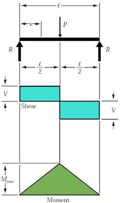
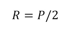
The simple beam has two supports at each end. These supports or reactions (R) are not fixed, hence they are free to move. This affects how the loads will react with supports in terms of shear and it’s bending moment. If they were fixed, the shear and moment forces would react differently (explained later). The first case is concentrated load (P), which acts on the beam at its center. The value of the force at each reaction is equates to the load at the center:
where P is the value of the load force.
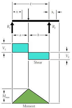
For the case of the concentrated load at the center, the shear stress (V) has the same value as the reaction force (R=V). One creates the shear diagram by analyzing the forces acting on the beam from one side to the other. If we start on the left, the reaction forces push up on the beam. This translates into the shear diagram as rising to the same value and going across with no slope until it reaches the center load. The shear value then is directed down the same value as the center load and continues across with no slope until it reaches second reaction load on the other end of the beam.
The moment is determined in a similar fashion. The slope of the moment diagram over the interval 0
where l is the length of the beam.
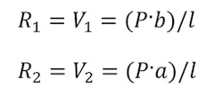
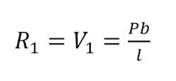
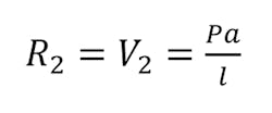
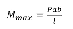
If the load was not centrally located, the value of R would be determined by its location. Let’s assume that the load P is not in the center, but a distance value a from the left and a distance value b from the right. The reaction values would be determined by:
Using the equations above for the reaction loads, you could alter the previous formulas as required.
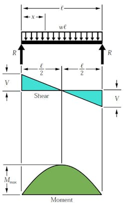
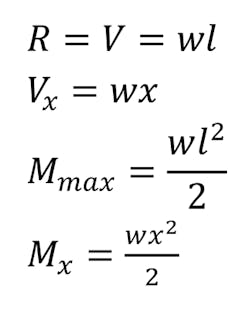
A different loading case is a uniformed load. The load is equally distributed across the length of the beam. The distributed load is quantified as load per distance (i.e., 10 kN-m) and can also be equated as a concentrated load at a specific point along the bar. The magnitude of the force is equal to the area under the curve of the distributed load, and the location is at the center of mass of the distributed load. For this case, the force at the reactions, which is also the maximum shear force, is expressed by:
where w is equal to the distributed load.
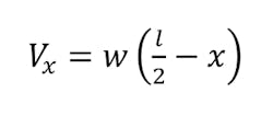
Here the shear diagram and the moment diagram change slightly. In the first case, the shear diagram is straight across until it encounters the load and shifts to the opposite direction. The shear in the second case is continuous negative slope. To find the shear force at any point, use the equation:
The maximum moment can be determined by:
Fixed Beam
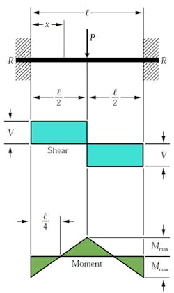
For a fixed beam, the difference will be seen in the moment diagram. The reaction forces are the same as in the simple beam:
where P is the value of the load force.
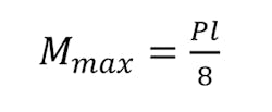
The shear diagram will also behave as found in the first case of the simple beam. However, now that the ends are fixed, the moment at the supports will reach differently. The moment at the center and at the ends can be expressed using the same equation:
Overhanging Beam
The overhanging beam has the first support at the beam’s end while the second support is located along the beam toward the center. In this particular example, the portion of the beam that passes the second support does not experience shear or bending. The visual depiction of shear and bending is similar to the simple beam. However, since the example above does not have a center load, the shear calculations will be different for each support:
(max shear value when a < b)
(max shear value when a > b)
Maximum moment is calculated by the following equation:
Double Overhanging Beam
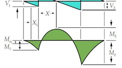
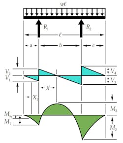
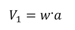
The double overhanging beam is the same concept as the single, except with both supports located along and within the beams length. In this case, the load across the beam is a uniformed load and impacts the shear and bending diagrams in a more complicated way. From left to right, the first shear value is determined by the distance of the first support to the end multiplied by the uniformed load.
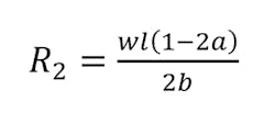
The reaction load at the first support is determined by:
where b and c are distances between supports and the remaining edge distance, respectively.
The shear value then changes at the first support location and is determined by the difference between the first shear value and the first support load:
Continuing left to right, the reaction load at the second support is:
Now the third shear value can be calculated as:
where V4 is the shear caused by the uniformed load at the right side overhanging edge:
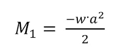
The momentum profile is much different in this case. As a result of the support locations, three different momentums take place. Using the same principle as we did for shear, we can analyze the moment values from left to right. The first bending moment is calculated simply by:
The next moment, which is M3 in the example above, is calculated with the following equation:
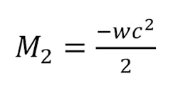
The final moment, M2, is determined by:
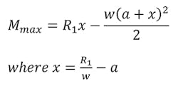
These are the three moments acting on the beam for this case. Maximum moment is determined by:
Continuous Beam
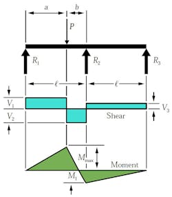
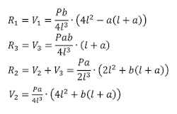
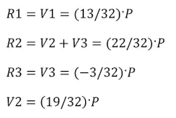
A continuous beam is a beam that is loaded and has more than two supports. These beams will experience loading cases like those discussed previously; however, they will be comprised of one or more cases. In the example for this beam, the point load is a concentrated load at any location in between two of the three supports. The following equations are the load values for the reactions:
The maximum bending moment at the point of the load is:
One could substitute the values a and b with equal distance values, l/2. The equations simplify to:
Cantilever Beam
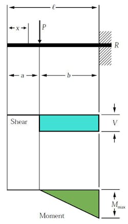
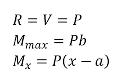
The cantilever beam will be the last case we analyze. The beam in this example is fixed into the wall and has a concentrated load acting upon it. The bending moment takes place around the fixed end. The shear and moment values are simply calculated by:
when x > a.
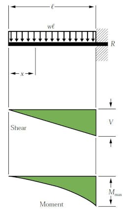
The beam in the image above is also a cantilever beam, but it’s exposed to a uniformed load. The equations for this example, which take into account the uniformed load, can be expressed as:
