What’s the Difference Between Stress-Strain Curves and Stiffness-Strain Curves?
Engineers have long used stress-strain curves to uncover a host of material properties. The curves are created by plotting the results of tensile strength tests of material samples, putting stress (force divided by area) on the y-axis and strain (stretch divided by gage or original length) on the x-axis. Some of the key material properties the curve can reveal include the material’s elastic limit, along with the elastic and plastic ranges, the yield point, ultimate and rupture strengths, and the moduli of resilience and toughness.
Sometimes, however, engineers must interpolate between data points to get those performance figures. Often a stiffness-strain curve tensile test result defines some material properties more precisely—no interpolating or “guesstimation” needed. It puts stiffness (change in stress divided by change in strain) on the y-axis and strain on the x-axis. In effect, it graphs the slope of the stress-strain curve as a function of strain.
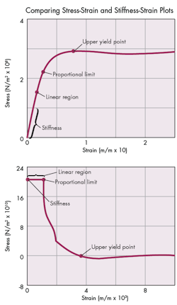
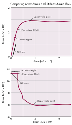
The two graphs on the left, for example, show the stress-strain curve (above) and the stiffness-strain curve (below) of a low-carbon steel. On the traditional stress-strain curve, engineers must measure the slope of the initial portion of the curve to determine the stiffness. On the stiffness-strain curve, however, engineers directly take the y-intercept as the stiffness value.
The stiffness-strain plot uses the same data as the stress-strain curve, but for the clearest representation, engineers might need to use an expanded scale. They can do this by using more data points from the test results on curved portions and parts of the graph with the features of interest. Or they can increase the number of data points by using a program that generates intermediate point as using a suitable interpolation algorithm.

